Support frame for an embolic protection device

a protection device and support frame technology, applied in the field of embolic protection devices, can solve the problems of inability to achieve the optimum performance of the device, inability to meet the needs of patients, and large support area, so as to reduce the diameter, facilitate the deployment of the medical device, and minimise the dampening effect of the radiopaque material

Inactive Publication Date: 2006-05-02
SALVIAC
View PDF547 Cites 125 Cited by
  • Summary
  • Abstract
  • Description
  • Claims
  • Application Information

AI Technical Summary

Benefits of technology

[0094]In addition, small wires enable greater flexibility for the filter element, which allow for ease of advancement through the vascular system.
[0136]In a further embodiment of the invention the support comprises a jacket around the filaments. The jacket helps to maintain the structure of the multifilament wire construction intact and ensure the filaments move in a coordinated manner. Preferably the filaments are embedded within the jacket. Ideally the jacket is at least partially of a radiopaque material. The jacket may be at least partially of a polymeric material.

Problems solved by technology

However, there exist a number of problems with some of the known devices.
In particular, upon collapse of the filter support, prior to delivery of the embolic protection device into and / or retrieval from a vasculature, large, localised stresses may be induced in the support.
Solutions to this problem heretofore may result in features which inhibit the optimum performance of the device.
In general conventional devices are not highly trackable because of their length in the wrapped delivery configuration.

Method used


Image

  • Support frame for an embolic protection device
  • Support frame for an embolic protection device
  • Support frame for an embolic protection device

Examples


Embodiment Construction

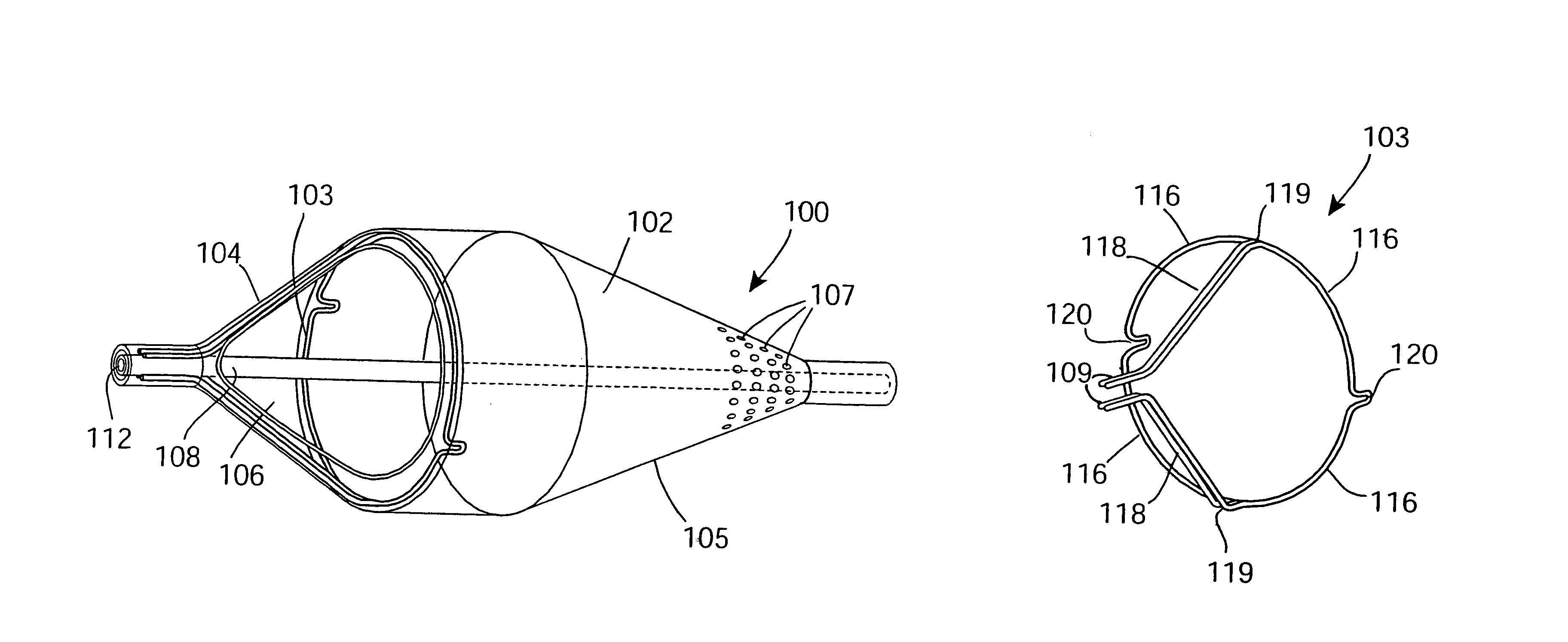
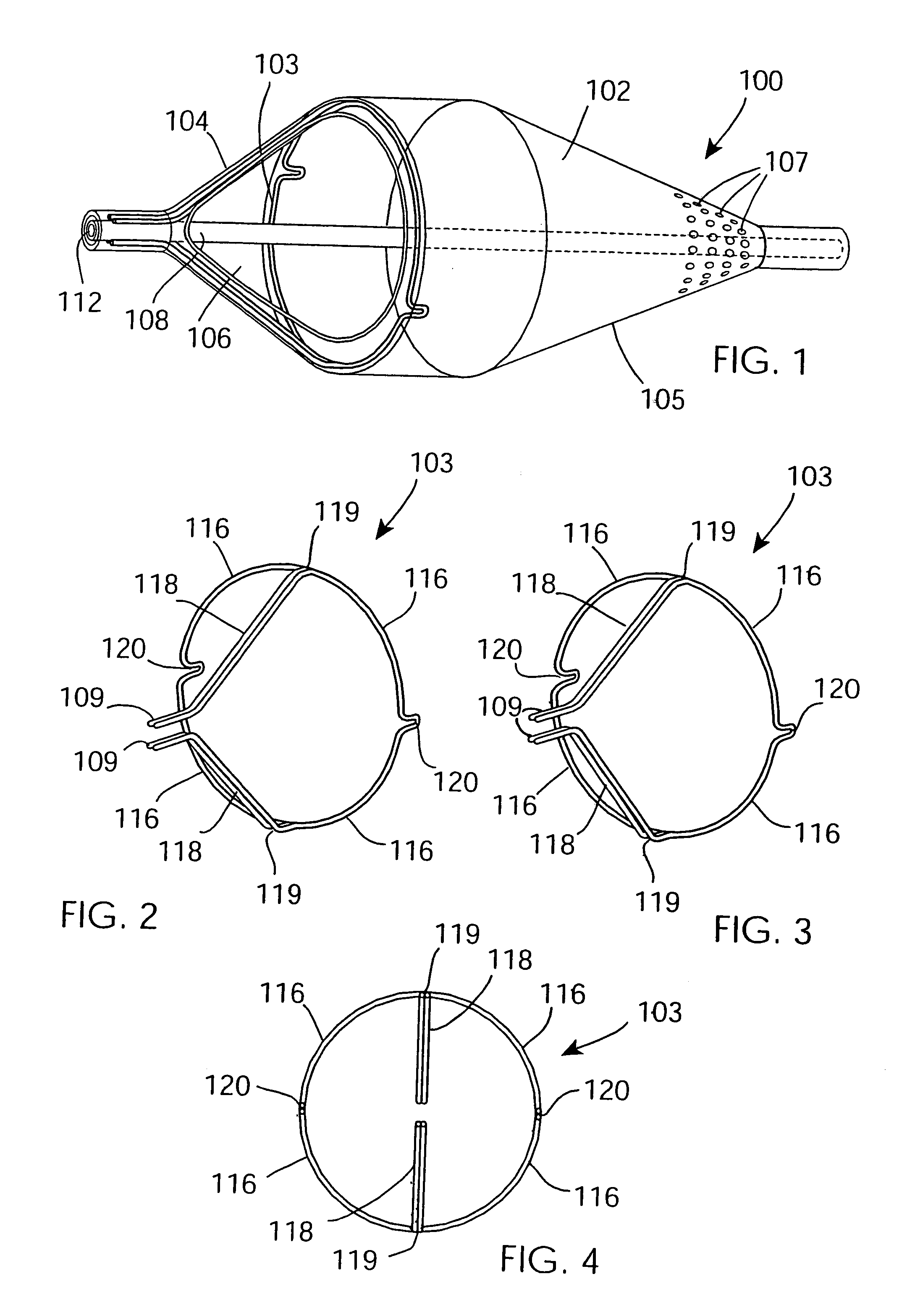
[0248]Referring to the drawings, there are illustrated several embolic protection devices according to the invention. In general the embolic protection devices comprise a collapsible filter element for delivery through a vascular system of a patient. The filter element comprises a collapsible filter body 102 and a filter support 103 for the filter body 102, and a carrier which may comprise a tubular member 108 to which the filter support 103 may be mounted. The filter body 102 has an inlet end 104 and an outlet end 105. The inlet end 104 has one or more large inlet openings 106 which are sized to allow blood and embolic material enter the filter body 102. The outlet end 104 has a plurality of small outlet openings 107 which are sized to allow through passage of blood but to retain undesired embolic material within the filter body 102. In this way, the filter element captures and safely retains any undesired embolic material in the blood stream within the filter body 102 while facili...


PUM


Abstract

A support 103 for an embolic protection device comprises round wires 116 which may form one or more support hoops for a filter body. The circumferential hoop formed by the wires 116 ensures that in the expanded position, the filter body 102 will be supported by the support frame 103 in circumferential apposition with the interior wall of the vasculature. The wires 116 may have a strain distributing linkage element in the form of a loop 120 in. The loop 120 acts as a diameter or circumference adjuster allowing an embolic protection device to adapt to different vessel contours and sizes whilst maintaining apposition with the vessel wall. The strain relieving geometry of the loops enhances the compliance of the bend points without creating a weakened hinge point, thus ensuring that there is no discontinuity in the circumferential seal against the vessel wall.

Description

CROSS REFERENCE RELATED APPLICATIONS[0001]This application claims the benefit of U.S. Provisional Application Nos. 60 / 341,836, filed Dec. 21, 2001, 60 / 341,805, filed Dec. 21, 2001, 60 / 373,641, filed Apr. 19, 2002, 60 / 373,640, filed Apr. 19, 2002, and 60 / 377,248, filed May 3, 2002, the contents of all of which are incorporated herein by reference.INTRODUCTION[0002]This invention relates to an embolic protection device. In particular, it relates to an embolic protection device of the type comprising a collapsible filter body to capture embolic material, and a support to maintain the filter body in an expanded position when the embolic protection device is deployed in a vasculature.[0003]Embolic protection devices of this general type are known.[0004]However, there exist a number of problems with some of the known devices. In particular, upon collapse of the filter support, prior to delivery of the embolic protection device into and / or retrieval from a vasculature, large, localised str...

Claims


Application Information

Patent Timeline
Patent Type & Authority Patents(United States)
IPC IPC(8): A61M29/00A61F2/01
CPCA61F2/013A61B2017/2212A61B2017/2215A61F2230/0093A61F2002/018A61F2230/0067A61F2002/016A61F2/0108
Inventor BRADY, EAMONVALE, DAVIDKELLLY, RONALDNEILAN, JOHNHORAN, STEVENRABITTE, GERARDMCCAFFREY, GERRY
Owner SALVIAC
Why Eureka
Try Eureka