Audio signal phase detection system and method

a phase detection and phase detection technology, applied in the direction of stereophonic circuit arrangements, transducer details, electrical transducers, etc., can solve the problems of serious degradation of sound quality, deterioration of sound quality, destructive interference, etc., to reduce the generation of high frequency components, and reduce the effect of signal filtering requirements within the signal sour

Inactive Publication Date: 2006-05-02
LEETRONICS CORP
View PDF10 Cites 23 Cited by
  • Summary
  • Abstract
  • Description
  • Claims
  • Application Information

AI Technical Summary

Benefits of technology

[0008]One implementation of an active signal generator includes a microcontroller generating the test signal waveforms in a digital representation, a digital to analog converter converting the digital representation of the test signal to an analog representation and an amplifier amplifying and filtering the analog representation of the test signal to provide an output analog signal. The audio signal source generates the first frequency component as a sine wave having a frequency in the range of 100 to 300 Hertz. The frequency should be within the frequency range of the audio system, yet low enough that the first frequency component is readily distinguishable from the second, higher frequency component that is also within the frequency range of the audio system. Selection of a signal frequency in this low frequency range permits testing of the low frequency response of the audio system, which may invert the phase of low frequency signals if the low frequency response is inadequate.
[0009]The second, higher frequency component is implemented in a preferred embodiment as a 2 KHz sine wave that is modulated with the positive half cycle of a 400 Hertz sine wave. The integer frequency ratio of 5:1 enables exactly 5 half cycles of the 2 KHz signal to occur during each positive half cycle of the 400 Hertz signal. This enables both the 400 Hertz half cycle and the 2 KHz signal to begin and end at zero magnitude so as to minimize the generation of high frequency signal components. Modulation of the 2 KHz signal with the positive half cycle of the 400 KHz signal further reduces the generation of high frequency components. Signal filtering requirements within the signal source are thus reduced.
[0010]Short bursts of the second, high frequency signal are added to the first, low frequency signal during portions of selected cycles of the first, low frequency signal that occur near the positive peak of the low frequency signal to mark the positive half cycle of the first, low frequency signal (alternatively, the negative half cycle could be marked). Because many speakers produce a physical resonance or ringing in the higher frequency ranges around 2 KHz, it is desirable to generate the second, higher frequency marking signal no more frequently than 100 times per second and more preferably, no more frequently than 50 times per second. This affords time for the resonance from one marking pulse to decay before a next marking pulse is generated.
[0013]Alternatively, a speaker output from the signal source may be acoustically coupled to a microphone input to the audio system for testing the phase of the microphone coupling. In this configuration electrical coupling of the phase detector to the amplifier is preferred over acoustic coupling to a speaker to avoid the phase shift and other distortion and signal losses that result from two acoustic couplings.

Problems solved by technology

If a phase reversal occurs, the input may still produce an intelligible output, but the output will experience a deterioration in sound quality.
If two or more speakers are out of phase with each other, the acoustic waves from different speakers will experience destructive interference and the sound quality will be seriously degraded.
While maintenance of proper phase relationships among audio signals should be technologically feasible, in practice this is a significant problem.
The problem is particularly acute when modular units in an audio system are acquired from different manufacturers.
There are no uniformly adopted standards for maintaining correct signal phase across connector jacks or even between inputs and outputs.
The lack of standards for manufacturing cable connectors can cause polarity connection errors which must be corrected before a recording session begins.
While systems do exist to detect phase reversals, these systems tend to be relatively expensive.
Such detectors are particularly expensive in the context of a nonprofessional who may change an audio system relatively infrequently to add a new component or update an existing component.

Method used


Image

  • Audio signal phase detection system and method
  • Audio signal phase detection system and method
  • Audio signal phase detection system and method

Examples


Embodiment Construction

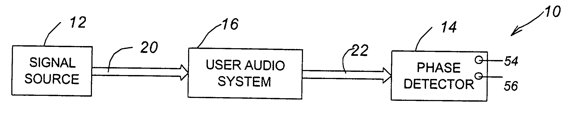
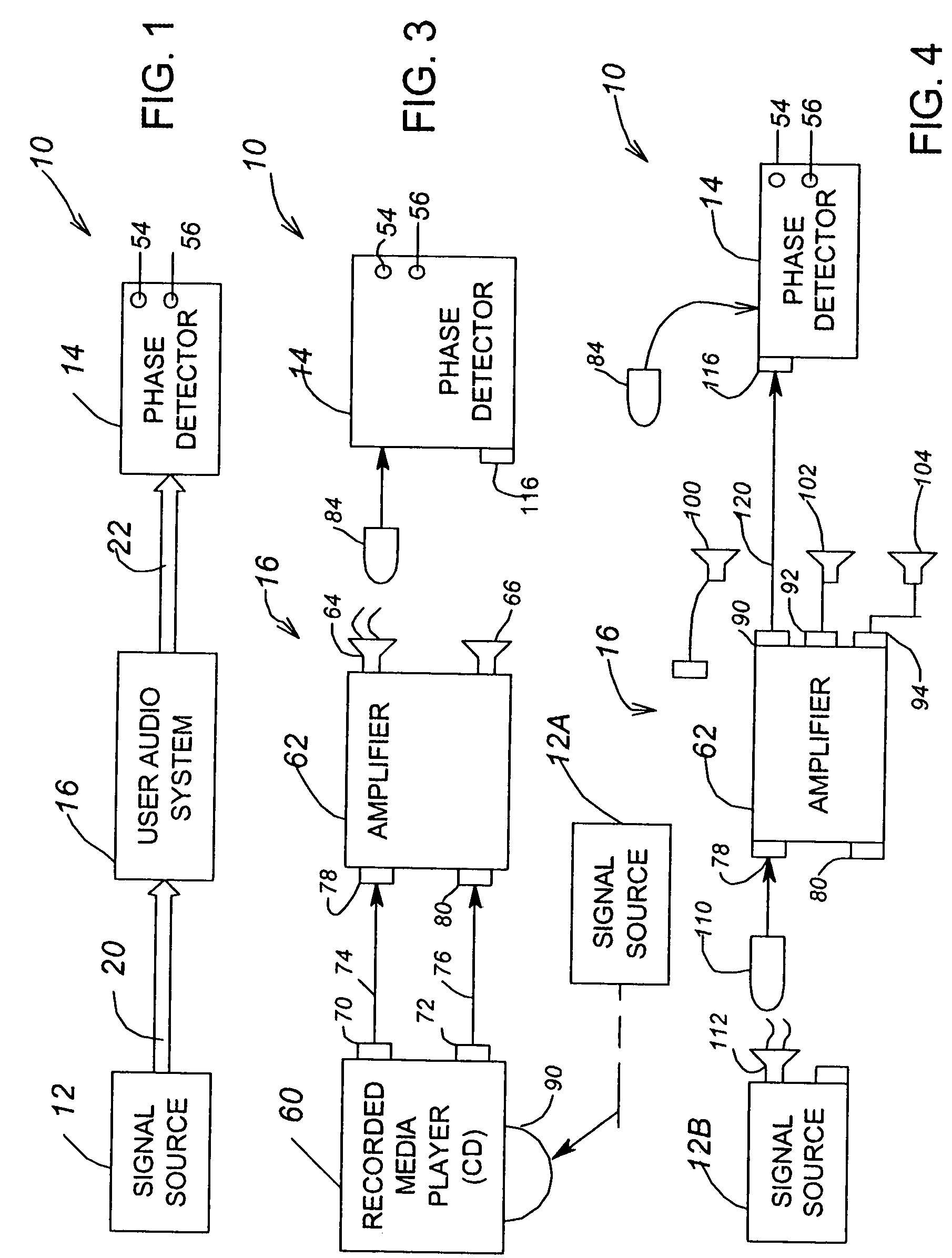
[0030]Referring now to FIG. 1, an audio signal phase detection system 10 in accordance with the invention includes a signal source 12 and a phase detector 14 coupled to a user audio system 16. A connection 20 represents a generalized coupling of a test signal generated by signal source 12 to the user audio system while a connection 22 represents a generalized coupling of a representation of the test signal produced by user audio system 16 in response to the original test signal to the phase detector 14. Audio system 16 may be a simple audio amplifier component of a home entertainment system, a complete audio video entertainment system, a professional system having both audio and video portions, a complex multi-input, multi-speaker audio system for a theater or amphitheater or other audio system or audio portion of a user system for which a user desires to test for signal phase reversals between an input and an output.

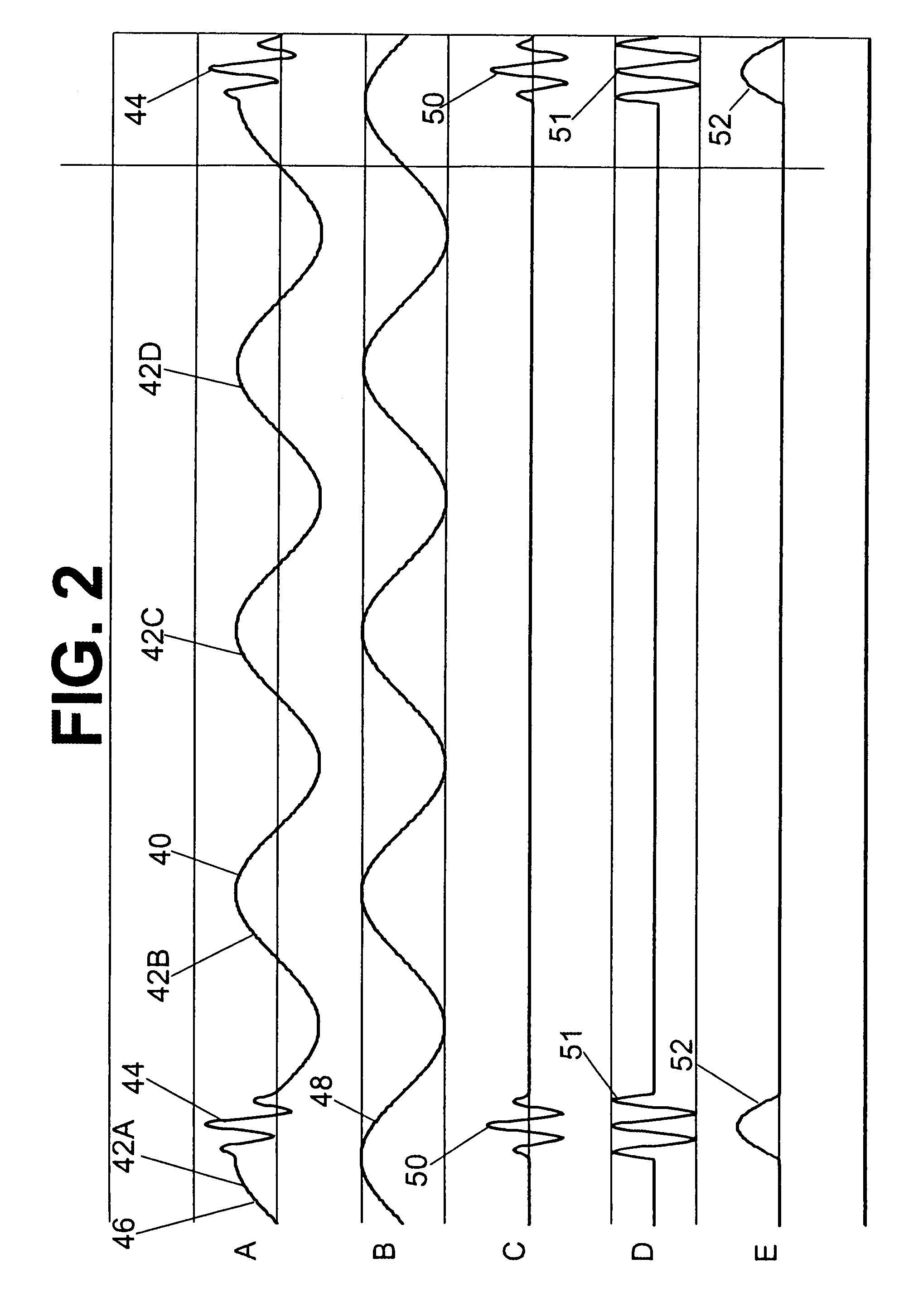
[0031]As shown in FIG. 2A, the signal source 12 generates a test s...


PUM


Abstract

A low cost, reliable and accurate audio frequency phase detection system and method includes an audio signal source generating an audio frequency test signal and a phase detector detecting phase reversals in the audio frequency test signal. The signal source may be an active, real time signal generator or a recorded media player playing back a prerecorded signal. The test signal is provided to a user system while the phase detector determines whether or not a phase reversal has occurred in the test signal between the input and output of the user system and illuminates a green or red LED to indicate whether or not a phase reversal has occurred. The test signal includes a lower frequency signal component and a higher frequency signal component that provides a marker for testing the phase of the lower frequency signal component.

Description

BACKGROUND OF THE INVENTION[0001]Proper operation of an audio system requires the maintenance of a correct signal phase to all speakers in the system. For optimum sound quality, a proper phase relation ship should be maintained both between each input and the signal processor (e.g., amplifier) as well as between the signal processor and each output. A positive pulse amplitude at a system input should produce a corresponding positive pulse amplitude at each system output, such as each speaker driver and the acoustic output signal from each speaker. If a phase reversal occurs, the input may still produce an intelligible output, but the output will experience a deterioration in sound quality.[0002]Similarly, each speaker should be in phase with all of the other speakers. If two or more speakers are out of phase with each other, the acoustic waves from different speakers will experience destructive interference and the sound quality will be seriously degraded.[0003]While maintenance of ...

Claims


Application Information

Patent Timeline
Patent Type & Authority Patents(United States)
IPC IPC(8): H04R1/40
CPCH04S7/40H04R1/403H04R5/04H04S1/002H04S3/002H04R29/001
Inventor LEE, BARRY THOMASBODIN, LESLIE JACK
Owner LEETRONICS CORP
Why Eureka
Try Eureka