Code converter, encoder, image output device and method thereof
a code converter and encoder technology, applied in the field of compression techniques, can solve the problems of inability to improve the processing of uncompressed data, and the inability to process the amount of uncompressed data. simple and reliably
- Summary
- Abstract
- Description
- Claims
- Application Information
AI Technical Summary
Benefits of technology
Problems solved by technology
Method used
Image

Examples
first embodiment
[First Embodiment]
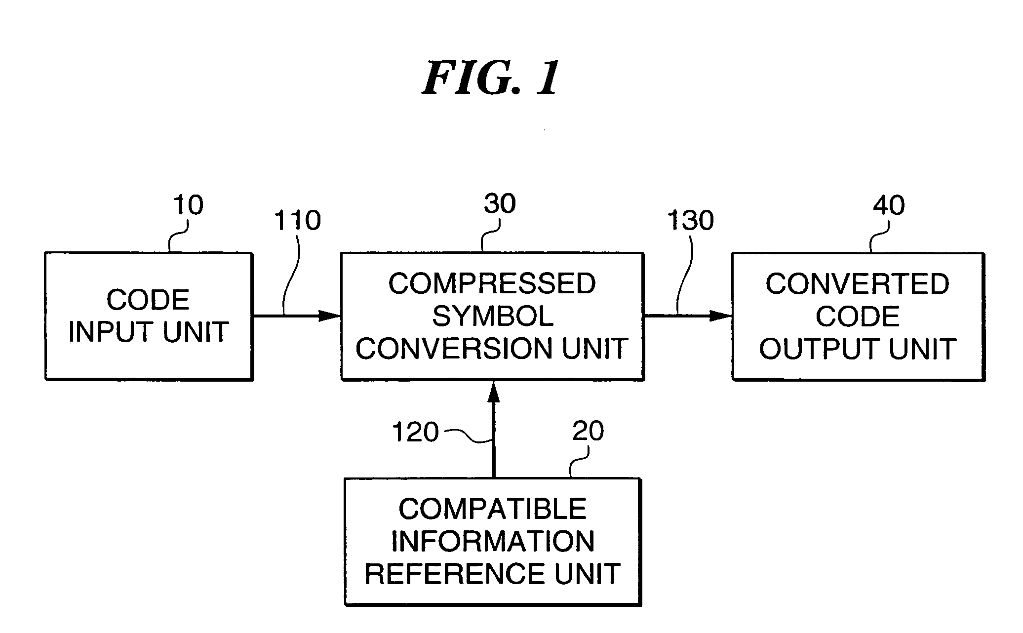
[0067]As a first embodiment of the present invention, an example embodied as a typical code converter will be described. The first embodiment of the present invention will be described specifically. FIG. 1 is a block diagram showing a code converter in the first embodiment. In the drawing, the same parts asFIG. 12 are indicated by similar numerals, and the description thereof is omitted. In the drawing, the numeral 20 denotes a compatible information reference unit, the numeral 30 denotes a compressed symbol conversion unit, and the numeral 120 denotes compatible information data.
[0068]The respective parts of FIG. 1 will be described. The compatible information reference unit 20 refers to compatible information of each compressed symbol before and after code conversion, which then sends out the compatible information data 120 to the compressed symbol conversion unit 30. The compressed symbol conversion unit 30, based on the compatible information data 120, converts...
second embodiment
[Second Embodiment]
[0086]As a first embodiment of the present invention, an example which embodies the present invention as an encoder will be described.
[0087]A second embodiment of the present invention will be described specifically. FIG. 6 is a block diagram showing an encoder in the second embodiment of the present invention. In the drawing, the same parts as FIGS. 12 and 1 are indicated by similar numerals, and the description is omitted. The numeral 16 denotes a data input unit, the numeral 31 denotes an encoding unit, and the numeral 116 denotes input data.
[0088]The respective parts of FIG. 6 will be described. The data input unit 16 inputs data to be encoded from outside, which then sends out the input data 116 to the encoding unit 31. The encoding unit 31 encodes the input data 116 by a predetermined method based on compatible information data 120, which then sends out the converted code data 130 to the code output unit 40.
[0089]The operation of the second embodiment of the...
third embodiment
[Third Embodiment]
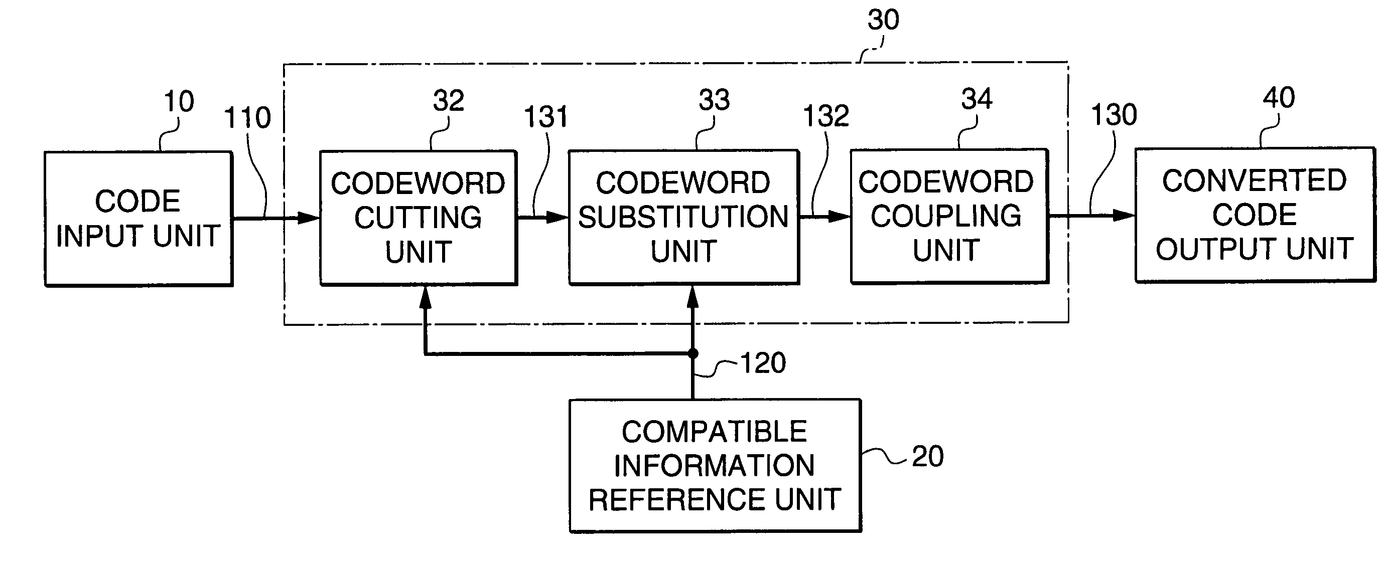
[0097]As a third embodiment of the present invention, an example in which the present invention is applied to a code converter of image encoding will be described. Taking the case of converting a codeword of the Huffman code of a multiple-value run length coder as an example, it will be described specifically.
[0098]The third embodiment of the present invention will be described specifically. FIG. 7 is a block diagram showing an image encoder of the third embodiment of the present invention. In the drawing, the same parts of FIGS. 12, 1 and 6 are indicated by similar numerals, and the description thereof is omitted. The numeral 32 denotes a codeword cutting unit, the numeral 33 denotes a codeword substitution unit, the numeral 34 denotes a codeword coupling unit, and the numerals 131 and 132 denote codeword data.
[0099]The respective parts of FIG. 7 will be described. The codeword cutting unit 32 cuts a codeword from input code data 110 based on compatible informatio...
PUM
 Abstract
Description
Claims
Application Information
 - R&D
- Intellectual Property
- Life Sciences
- Materials
- Tech Scout
- Unparalleled Data Quality
- Higher Quality Content
- 60% Fewer Hallucinations
Browse by: Latest US Patents, China's latest patents, Technical Efficacy Thesaurus, Application Domain, Technology Topic, Popular Technical Reports.
© 2025 PatSnap. All rights reserved.Legal|Privacy policy|Modern Slavery Act Transparency Statement|Sitemap|About US| Contact US: help@patsnap.com