Self-piercing rivet, process and device for setting a rivet element, and employment thereof

a self-piercing rivet and rivet element technology, applied in the direction of threaded fasteners, screwdrivers, manufacturing tools, etc., can solve the problems of inability to create self-piercing blind rivets, inability to pierce blind rivets, so as to prevent lateral displacement of the segment, and facilitate the opening of the die

Inactive Publication Date: 2006-05-09
NEWFREY
View PDF61 Cites 20 Cited by
  • Summary
  • Abstract
  • Description
  • Claims
  • Application Information

AI Technical Summary

Benefits of technology

[0052]The segments are so formed that they firstly are able to absorb great forces in the punching direction without becoming laterally unstable and e.g. slipping away, but in the second place, can be opened in simple manner by radial forces directed away from the punch opening and generated by the forming of a closure head.
[0053]In one embodiment of the die according to the invention, the segments are radially displaceable. A radial displacement of the segments effects an especially easy opening of the die. Alternatively, the segments are so formed, or so mounted on an axis, that the segments execute a rotary or tilting motion.
[0054]In an advantageous modification of the die according to the invention, the segments comprise a substantially plane bearing surface and the die mount a substantially plane matching surface for transmitting the punching forces to the die mount. Owing to the plane surfaces, great punching forces can be absorbed by the segments and transmitted to the die mount, ensuring a stable lodgment of the segments in the punching operation.
[0055]In a preferred embodiment of the die according to the invention, the segments comprise receptacles for spring elements. A spring element is guided in the receptacles. This makes it possible for the segments, after completion of a setting operation, to return into the

Problems solved by technology

Various “designs” have been developed for self-drilling blind rivets, but the creation of self-piercing blind rivets has not been considered, since the necessary deformability of the shank does not permit exertion of a piercing force.
A disadvantage of the blind rivet consists in that holes must be drilled or punched in the work in order to set the blind rivet.
This is difficult especially when two parts are to be connected to each other, the parts not being movable relative to each other.
Production of the holes in conjunction with orientation of the parts sometimes presents difficulties, so that the drilling and the setting of the rivet must take place in a fixed relative position of the parts.
Even in the case of the self-drilling b

Method used


Image

  • Self-piercing rivet, process and device for setting a rivet element, and employment thereof
  • Self-piercing rivet, process and device for setting a rivet element, and employment thereof
  • Self-piercing rivet, process and device for setting a rivet element, and employment thereof

Examples


Embodiment Construction

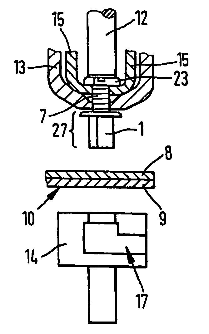
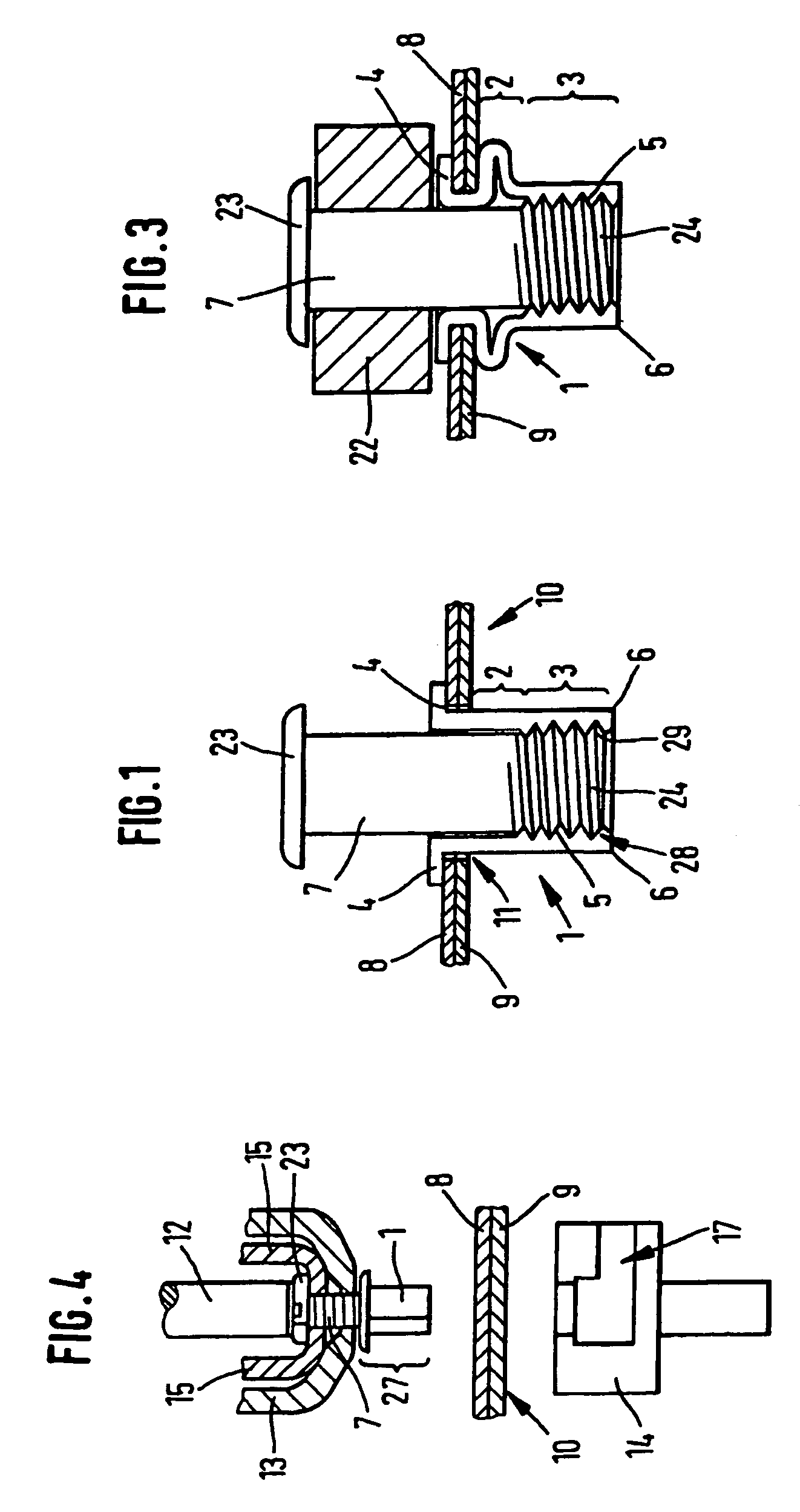
[0075]FIG. 1 shows a fastening element 1 according to the invention, having a setting head 4, a deformation segment 2 and a shaft end 3 with an internal thread 5 and a punching edge 6, hollow, into which a mandrel 7 having a head 23 and a foot 24 is screwed. The tension-resistant connection between the mandrel 7 and the shank 27 is made by means of a connecting segment 28. The connecting segment 28 is made up of an internal thread 5 in the shank 27. The internal thread 5 is screwed onto an external thread 29 on the mandrel 7. The fastening element 1 is punched through a first part 8 and a second part 9, the two parts 8, 9 having the aspect of sheets lying one upon another. The fastening element 1 punches its own hole 11 through the parts 8, 9. The shank end 3 and part of the deformable segment 2 are located in the rear 10 of the second part 9. The deformation segment 2 has a thin wall thickness compared to the shank end 3. The mandrel 7 includes a head 23, to which firstly accessori...


PUM

PropertyMeasurementUnit
Fractionaaaaaaaaaa
Distanceaaaaaaaaaa
Distanceaaaaaaaaaa

Abstract

A fastening element (1), in particular for blind riveting, has a setting head (4), a deformation segment (2) and a shank end (3). The deformation segment (2) is arranged between the setting head (4) and the shank end (3). The fastening element (1) is hollow, optionally having a mandrel (7) inside the fastening element (1). The mandrel includes a head (23) and a foot (24) at least tension-resistantly connected to the shank end (3). The shank end (3) includes a punching edge (6) extending substantially along the outermost periphery of the shank end (3). Also identified are a process for setting the fastening element (1), a riveted connection to the fastening element (1), a device for setting the fastening element (1), an employment of the riveted connection obtained, and a die suitable for setting the fastening element (1).

Description

CROSS-REFERENCE TO RELATED APPLICATIONS[0001]This application is a Continuation of International Application No. PCT / DE02 / 00764, filed Mar. 1, 2002. This application claims the benefit of German Patent Application 10160771.7 filed Dec. 11, 2001, German Patent Application 10121218.6 filed Apr. 30, 2001, and German Patent Application 10111692.6 filed Mar. 9, 2001. The disclosures of the above applications are incorporated herein by reference.FIELD OF THE INVENTION[0002]The invention relates to a fastening element, in particular a blind rivet, having a setting head, a deformation segment and a shank end, and to a process and device for setting the said fastening element, a punch die, the riveted connection made by the process and / or device, and an employment of said riveted connection.BACKGROUND OF THE INVENTION[0003]Numerous types of rivets are known in the art. Blind rivets are distinguished in that the force required to set the blind rivet is not applied by force-absorbing stirrups ...

Claims


Application Information

Patent Timeline
IPC IPC(8): B23Q15/00B23P19/00F16B13/04B21J15/00B21J15/02B21J15/04B21J15/36F16B19/08F16B19/10F16B29/00F16B37/06
CPCB21J15/025B21J15/043B21J15/36F16B19/086F16B19/1045F16B19/1072F16B37/067Y10T29/5343Y10T29/5118Y10T29/49956Y10T29/49833Y10T29/5377Y10T29/5307Y10T29/49776
Inventor MAUER, DIETEROPPER, REINHOLD
Owner NEWFREY
Why Eureka
Try Eureka