Shoe cleat

a technology for shoes and cleats, applied in the field of shoes, can solve the problems of limiting the deflection range, the 860 patent has a tendency to be clogged with grass blades and/or mud in the region, and the cleat is disclosed, so as to reduce the clogging of the structure and improve the traction efficiency

Active Publication Date: 2006-05-09
SOFTSPIKES
View PDF186 Cites 52 Cited by
  • Summary
  • Abstract
  • Description
  • Claims
  • Application Information

AI Technical Summary

Benefits of technology

[0009]Therefore, in light of the above, and for other reasons that become apparent when the invention is fully described, an object of the present invention is to provide an improved shoe cleat of the general type described in my '860 patent wherein traction efficiency is improved by minimizing clogging of the structure by grass or mud and by strengthening the traction elements of the cleat to resist tearing in response to lateral bending stress.
[0010]It is another object of the invention to provide an improved shoe cleat of the general type described in my '860 patent wherein additional structural support is provided to eliminate or limit lateral bending of the traction elements of the cleat.
[0011]Still another object of the invention is to provide an improved shoe cleat of the general type described in my '860 patent wherein clogging of the cleat with grass and / or mud between the traction elements and the cleat hub is substantially eliminated.
[0014]In accordance with the present invention, a resilient web is provided between adjacent traction elements. Each web has a convex upper surface and a concave lower surface, the upper convex surface being configured such that its apex abuts or is very closely proximate the outsole of the shoe when unstressed. The webs, being disposed around the hub periphery between traction elements, prevent grass and / or mud from entering the region between the traction element and the hub. Preferably, the webs are molded as an integral part of the cleat and therefore are made of the same resiliently flexible material that permits the traction element to resiliently flex under the weight of the wearer of the shoe. The webs thus flex in response to laterally applied forces to absorb the lateral stresses that would otherwise tend to tear the traction elements from the hub. In addition, the simple presence of the webs, apart from their flexure capability, provides lateral structural support for the traction elements.
[0015]In addition, the outer surfaces of the traction elements are contoured to maximize the pressure that traps grass blades against the shoe sole upon deflection of the traction elements. In the preferred embodiment of the invention the outer surface of each traction element is formed of two outwardly converging generally planar sections that intersect at a linear edge, or at a narrow strip, along the length dimension and at the outermost part of the traction element. Alternatively, the outer surface can be multi-faceted with plural intersections that provide respective localized forces. A further alternative is to configure the outer surface of the traction element as a segment of an elipsoid or other shape extending lengthwise along the traction element such that only a small area of the surface traps the grass blades against the shoe sole.

Problems solved by technology

Although exceptionally effective for its intended purpose, the cleat disclosed in my '860 patent has a tendency to become clogged with grass blades and / or mud in the region between the hub and the traction elements and between the traction elements themselves.
The clogging material, particularly grass blades which tend to wrap around the hub, limits the deflection range of the traction elements toward the shoe sole and thereby compromises the effectiveness of the cleat in providing traction.
In addition, the traction elements are subject to wear and possible tearing at the point of connection to the hub due transverse bending forces applied to the traction elements in use.
Such repeated lateral bending tends to weaken the junction between the hub and traction element until eventually the traction element tears loose from the hub.
Similarly, pivoting or turning of the shoe sole when under the weight of the wearer, results in similar lateral bending stresses in the front and back traction elements, with the ultimate weakening and tearing of the traction element.

Method used


Image

  • Shoe cleat
  • Shoe cleat
  • Shoe cleat

Examples


Embodiment Construction

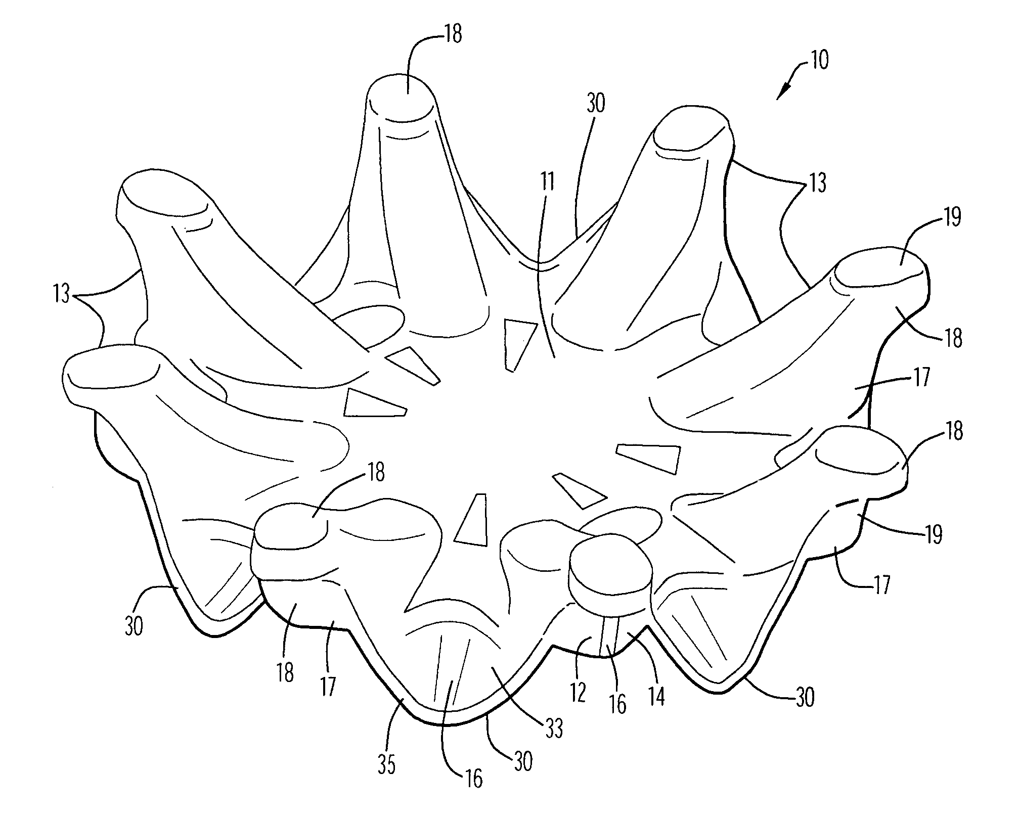
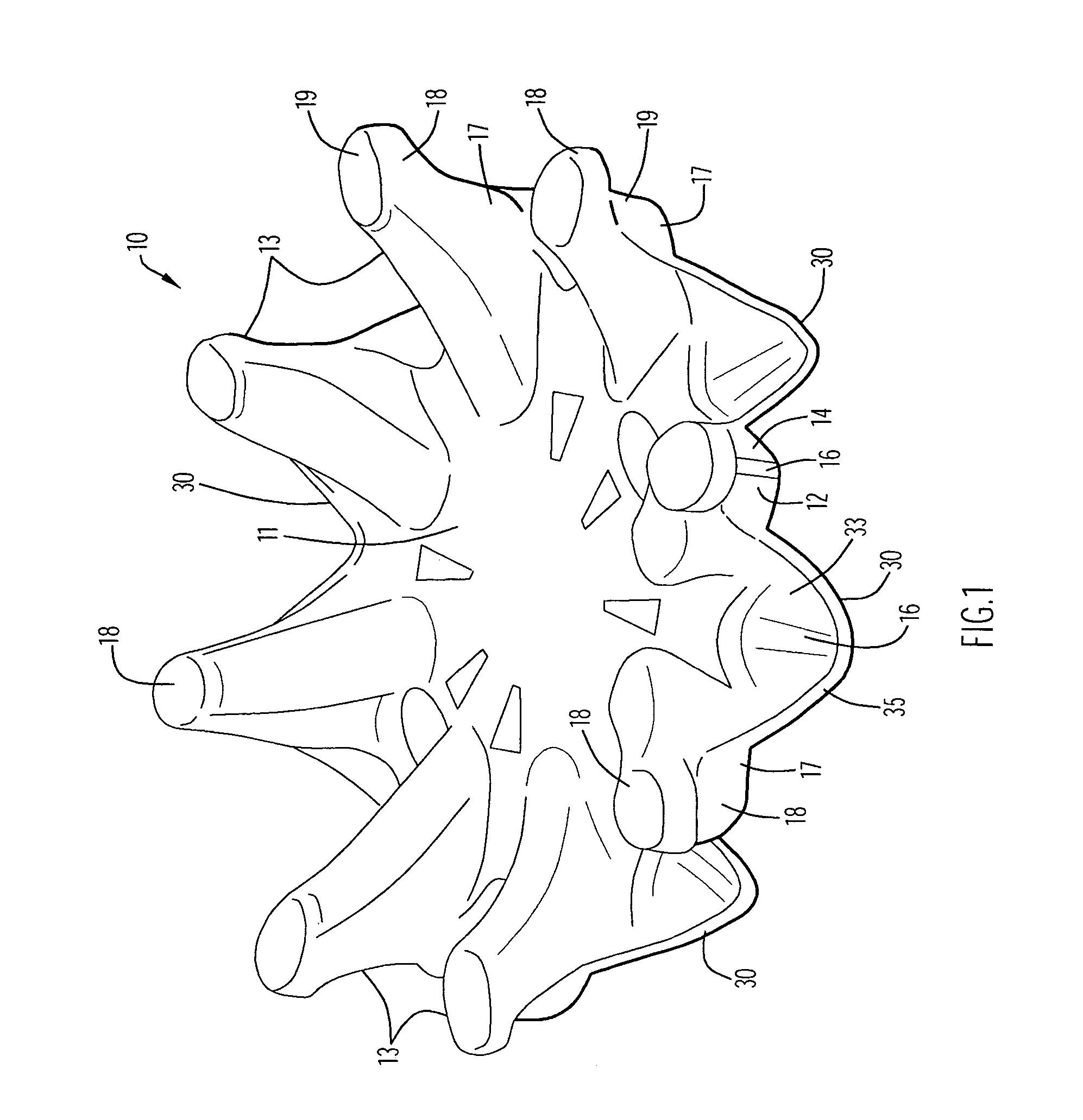
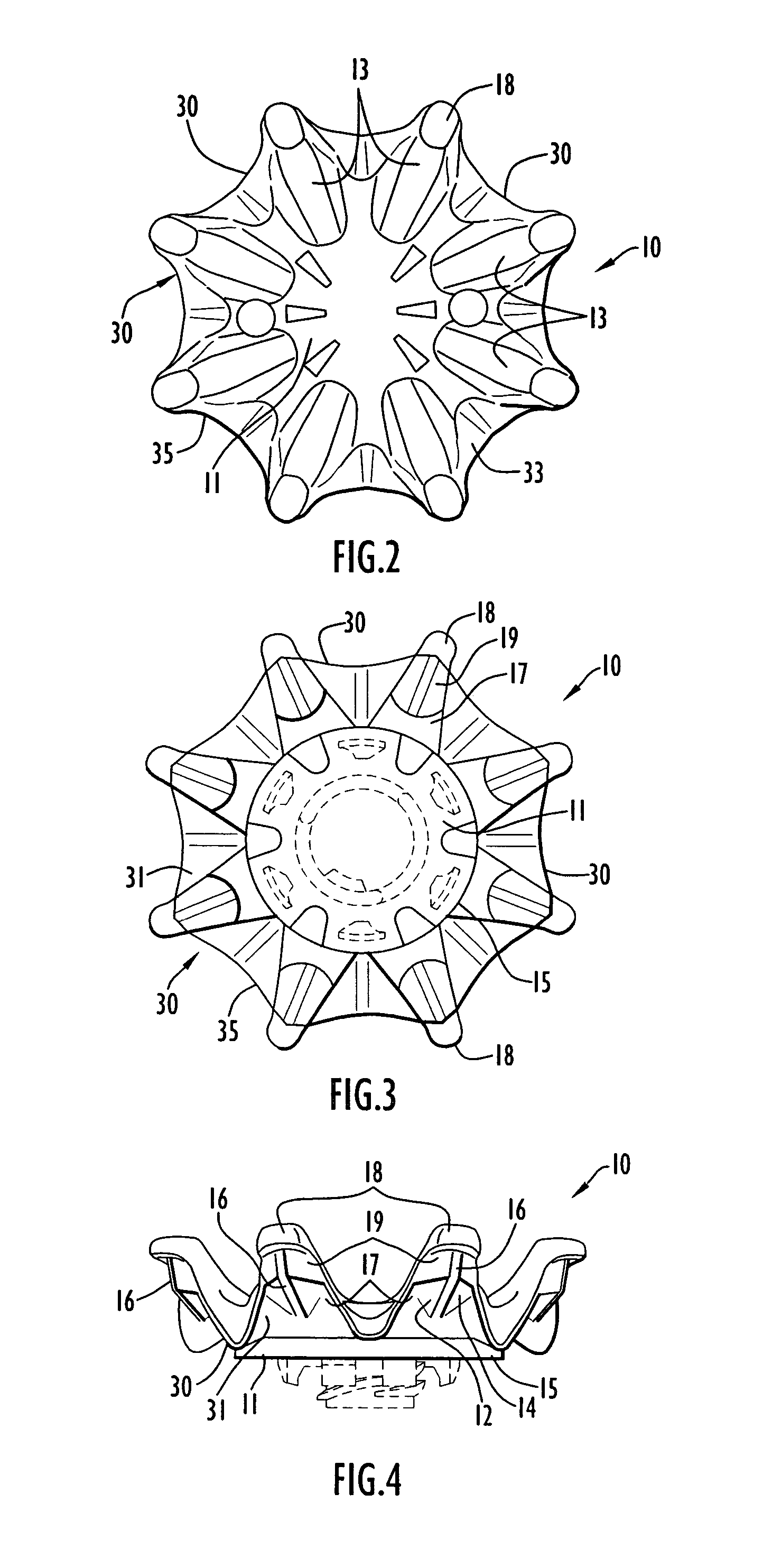
[0022]In accordance with the present invention, traction is provided for athletic activities on turf surfaces by providing an athletic shoe having cleats, each of which has a hub with a plurality of traction elements extending outwardly and downwardly from the hub with resiliently flexible webs extending between and connecting adjacent traction elements. The cleat also preferably includes an attachment member, male or female, such as a threaded stud or shaft or socket or other attachment device which may be integral with, or removable from, the central hub, for attaching the cleat to a corresponding mating attachment member, such as a threaded or other engagement socket or shaft secured in the sole of an athletic shoe. Each traction element is strengthened against tearing by the connecting webs, and the webs are positioned and configured to prevent clogging of the cleat with grass and / or mud in the region between the traction elements and the cleat hub.

[0023]Referring to FIGS. 1–5, ...


PUM


Abstract

An improved cleat for an athletic shoe provides for: enhanced strength and wear-resistance for the cleat traction element; and / or prevention of grass, mud and other debris from agglomerating and clogging the cleat. A resiliently flexible web is connected between adjacent traction elements to absorb the lateral and torsional forces tending to weaken the junctions between the cleat hub and the traction elements. The web is extended from the hub to prevent debris from entering the space between the shoe sole and the traction elements as well as between the traction elements themselves.

Description

CROSS REFERENCE TO RELATED APPLICATIONS[0001]This application claims priority from U.S. Provisional Patent Application Ser. No. 60 / 493,815, entitled “Shoe Cleat”, filed Aug. 11, 2003. The disclosure of this provisional patent application is incorporated herein by reference in its entirety.[0002]The present invention constitutes an improvement of the invention disclosed in my prior U.S. Pat. No. 6,023,860 (referred to herein as “my '860 patent”), the disclosure of which is incorporated herein in its entirety by this reference.BACKGROUND OF THE INVENTION[0003]1. Field of the Invention[0004]The present invention pertains generally to cleats for use with athletic shoes worn on turf and other surfaces. In particular, the present invention pertains to a golf cleat that provides improved traction and stability while minimizing clogging of the cleat by agglomerated soil, mud and grass.[0005]2. Discussion of the Related Art[0006]In my aforesaid '860 patent there is disclosed a removable clea...

Claims


Application Information

Patent Timeline
Patent Type & Authority Patents(United States)
IPC IPC(8): A43B5/02A43B5/00A43C15/16
CPCA43B5/001A43C15/168A43C15/162
Inventor MCMULLIN, FARIS W.
Owner SOFTSPIKES
Why Eureka
Try Eureka