
End surface capillary structure of heat pipe

a technology of capillary structure and heat pipe, which is applied in the direction of refrigeration equipment, lighting and heating equipment, heating and refrigeration combinations, etc., can solve the problems of poor thermal conduction, difficult to dispose of axial bars, and inability to manufacture by mass production

Inactive Publication Date: 2006-05-09
HSU HUL CHUN
View PDF10 Cites 21 Cited by
  • Summary
  • Abstract
  • Description
  • Claims
  • Application Information

AI Technical Summary

Benefits of technology

[0008]The present invention provides a heat pipe having an end surface capillary structure serving as a heat absorption portion. According to the heat pipe structure of the present invention, the axial bar is no more needed to fabricate the wick structure. Therefore, the drawback of above-mentioned process is resolved, while the powder-sintered wick structure of the heat pipe provides proper delivery of working fluid.

Problems solved by technology

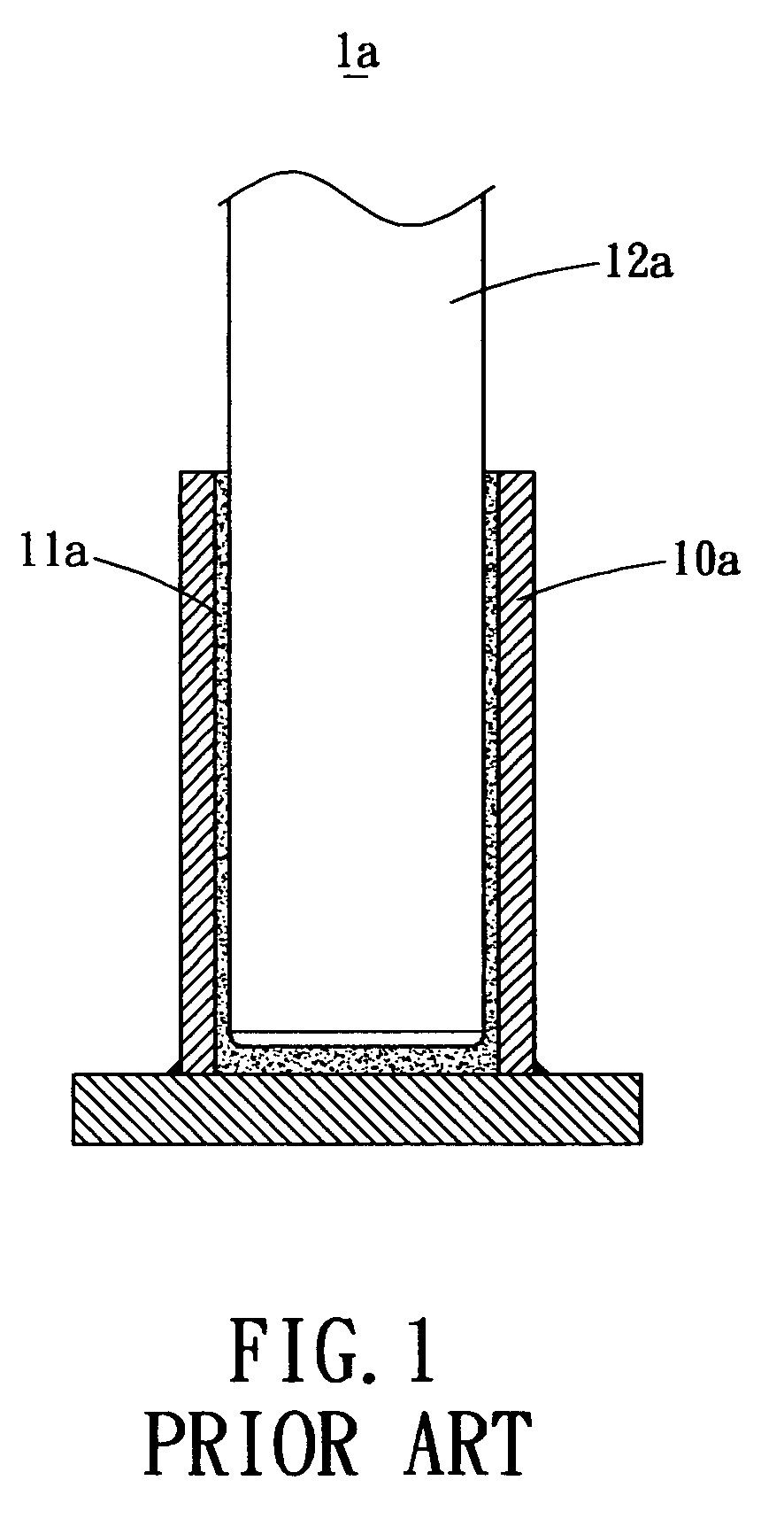
1. When the axial bar 2a is inserted into the pipe member 10a of the heat pipe 1a, it is difficult to dispose the axial bar 1a along the axis of the pipe member 10a. Instead the axial bar 1a is easily deviated from the axis to cause non-uniform wick structure 11a, such that the fluid transportation is non-uniform to cause poor thermal conduction.
2. After powder sintering process, the powders for forming the wick structure ha are easily attached to the axial bar 12a to cause problem for removing the axial bar 12a from the pipe member 12a. Therefore, the quality of such heat pipe depends on proficiency of the operator, and it cannot be fabricated by mass production.
3. As it is difficult to remove the axial bar 12a, external force is required for the removal. However, because an annealing process is performed on the wick structure 11a and the pipe member 10a before removing the axial bar 12a, the heat pipe 1a is extremely soft. Therefore, during the removal of the axial bar 12a, the pipe member 10a is easily deformed and the wick structure 11a is easily damaged. Such that the structure precision of the heat pipe 1a will be greatly affected.
Therefore, there exist inconvenience and drawbacks for practically application of the above-mentioned conventional heat pipe.

Method used


Image

  • End surface capillary structure of heat pipe
  • End surface capillary structure of heat pipe
  • End surface capillary structure of heat pipe

Examples


Embodiment Construction

[0020]Reference will now be made in detail to the preferred embodiments of the present invention, examples of which are illustrated in the accompanying drawings. Wherever possible, the same reference numbers are used in the drawings and the description to refer to the same or like parts.

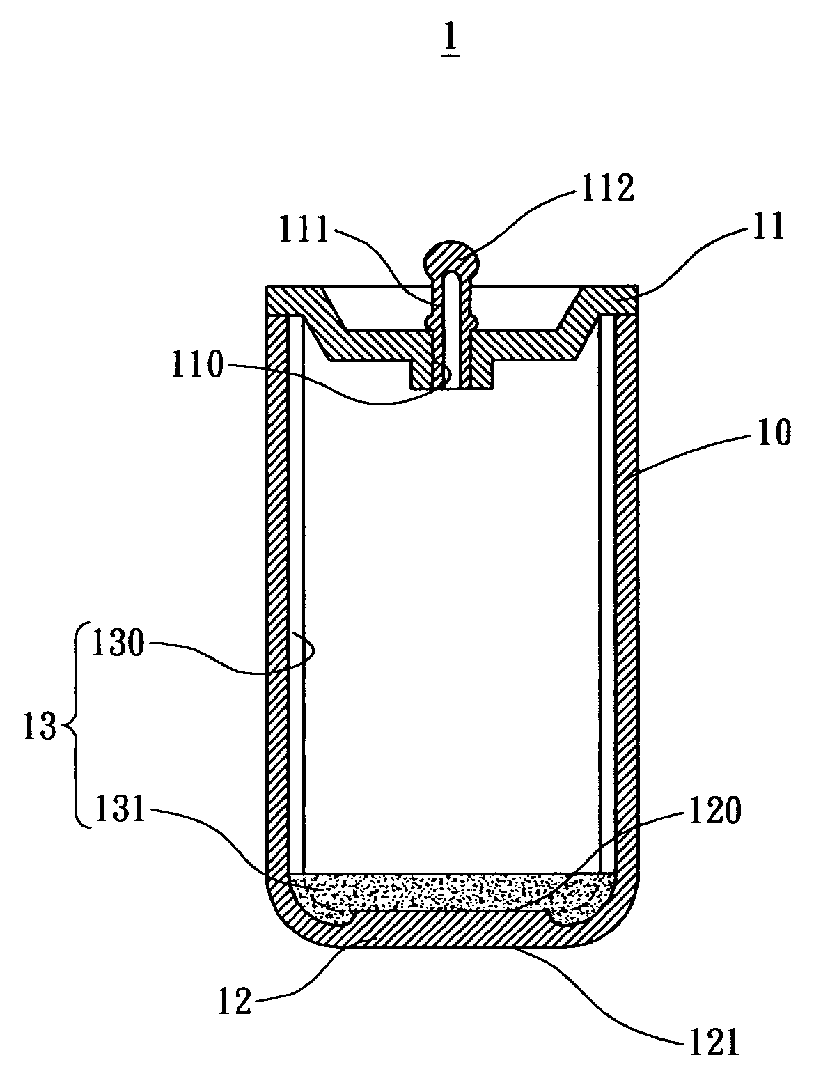
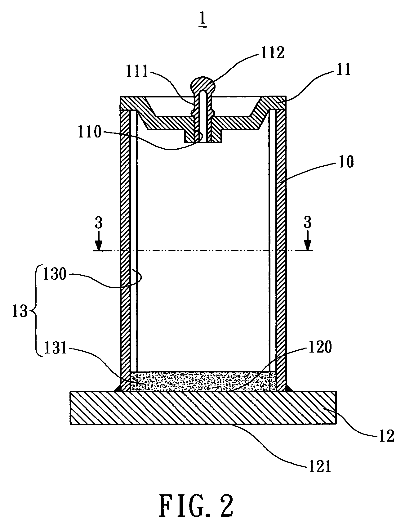
[0021]As shown in FIG. 2, a cross sectional view of a heat pipe provided by one embodiment of the present invention is illustrated. The heat pipe 1 includes a pipe member 10, a top lid 11 and a bottom lid 12.

[0022]The pipe member 10 is preferably a cylindrical hollow tube with one end covered by the top lid 11 and the other end connected to the bottom lid 12. The top lid 11 has an aperture 110 for receiving a filling tube 111; however in another preferred embodiment, the top lid 11 and the filling tube 111 can be integrally formed. Such that a working fluid can be filled into the pipe member 10 through the filling tube 111. By subsequent process such as vacuum, the aperture 110 is sealed with the sea...


PUM


Abstract

A heat pipe includes a pipe member, a bottom lid and a wick structure. The pipe member includes a plurality of longitudinal grooves radially arranged on an inner sidewall thereof. The bottom lid covers a bottom end of the pipe member. The wick structure includes the grooves and sintered powders attached to an inner surface of the bottom lid. Thereby, the sintered powders does not need to be attached to the inner wall of the pipe member so that an axial bar is no more need. Such that, the damage caused by removal of the axial bar are prevented and the fabricating process of the heat pipe is simplified.

Description

BACKGROUND OF THE INVENTION[0001]The present invention relates in general to an end surface capillary structure of a heat pipe, and more particularly, to a heat pipe that includes an end surface in contact with the heat source and a wick structure including a plurality of grooves and a powder-sintered attachment.[0002]Having the characteristics of high thermal conductivity, fast thermal conduction, light weight, non-movable components and simple structure, heat pipes are able to deliver large amount of heat without consuming electricity, and are therefore commonly used in the market.[0003]FIG. 1 illustrates a conventional heat pipe 1a that includes a pipe member 10a and a powder-sintered wick structure ha attached to an internal sidewall of the pipe member 10a. The wick structure 11a provides capillary force to transport working fluid filled in the pipe member 1a. However, the fabrication of the wick structure 11a requires an axial bar 12a inserted into the heat pipe 1a for supporti...

Claims


Application Information

Patent Timeline
Patent Type & Authority Patents(United States)
IPC IPC(8): F28D15/00
CPCF25B23/006F28D15/046F28D15/0283
Inventor HSU, HUL-CHUN
Owner HSU HUL CHUN
Learn More