
Semiconductor device by embedded package

a technology of semiconductor devices and embedded components, which is applied in the details of semiconductor/solid-state devices, semiconductor devices, electrical apparatus, etc., can solve the problems of damage to semiconductor chips, difficult fixation of semiconductor chips in the center of the inner bottom of the metal housing, and affect the filling buffer material, etc., to improve improve the effect of the structure of semiconductor devices and good fixing place for semiconductor chips

Inactive Publication Date: 2005-07-21
ACTRON TECH
View PDF14 Cites 0 Cited by
  • Summary
  • Abstract
  • Description
  • Claims
  • Application Information

AI Technical Summary

Benefits of technology

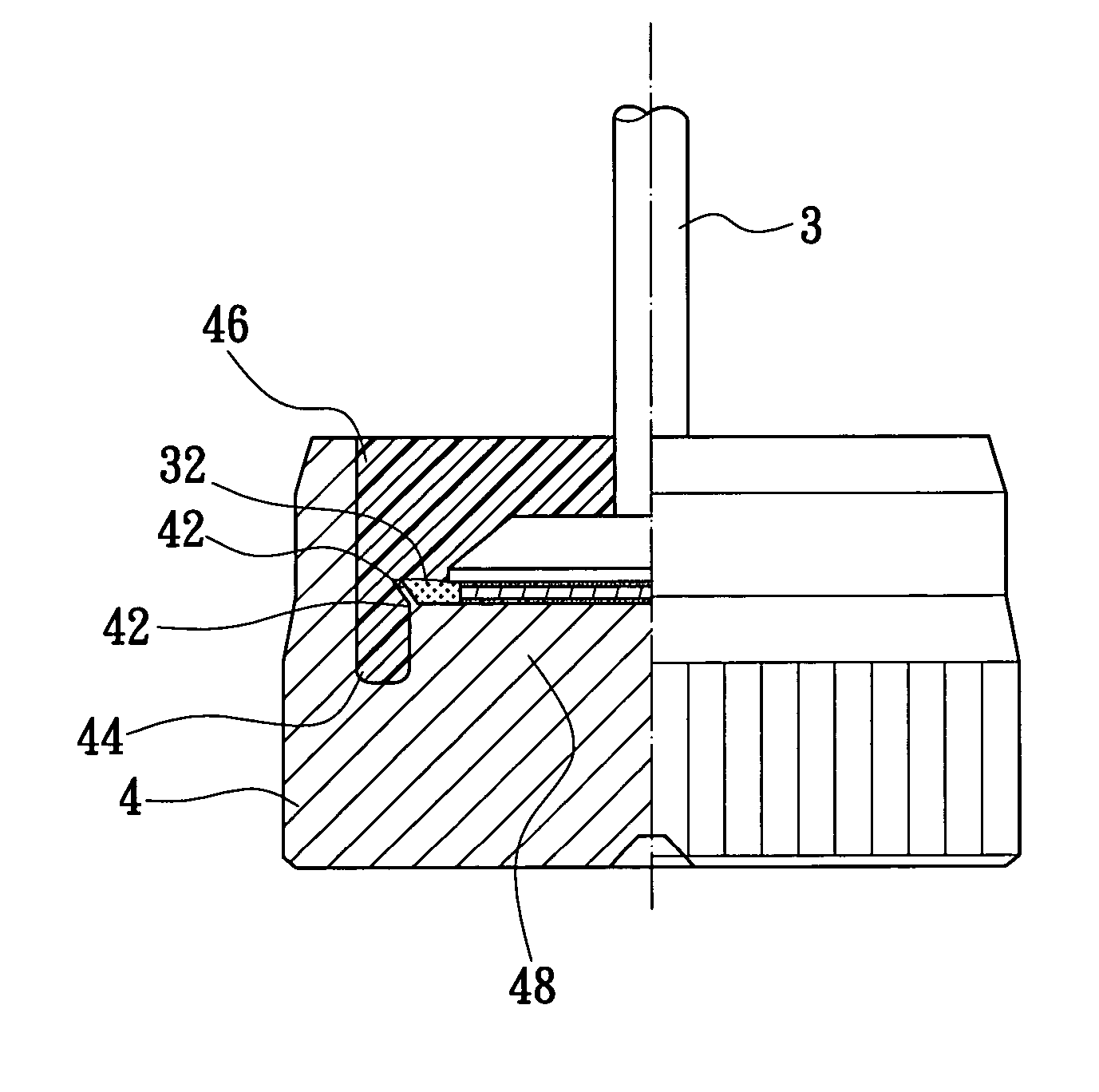
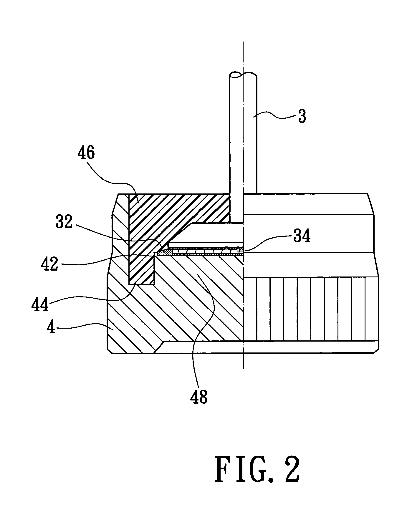
[0006] The main purpose of the present invention is to provide an improved structure of a semiconductor device serving as a power diode. The structure of new invention has a well inside to induce the stress during assembly to protect the semiconductor chip on the bonding stage. The structure of the present invention also provides a fence around the bonding stage to constrain the insulation glue. The bonding stage can further provide a good fixing place for the semiconductor chip. Thus the drawbacks of the conventional technique can be resolved. In short, the purpose of the present invention is to provide the semiconductor device for a power diode having good stress resistance during assembly, good insulation in a bonding area of the semiconductor chip, and a precise position for chip bonding.

Problems solved by technology

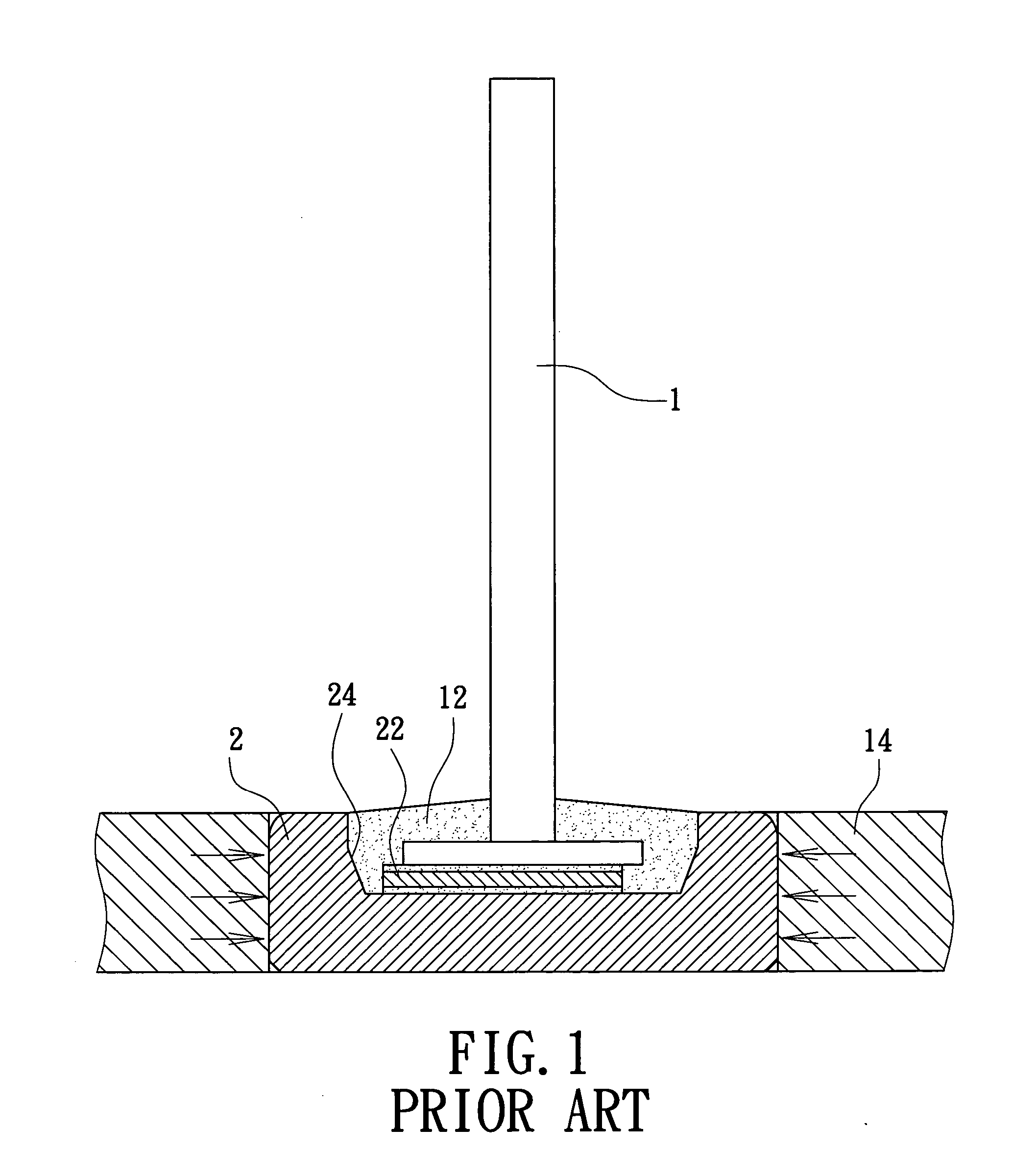
Firstly, the semiconductor chip 22 is very hard to fix in the center of the inner bottom of the metal housing 2.
Also, the filled buffer material may be affected by thermal shock or mechanical impact to generate cracks.
The cracks may allow moisture to enter the buffer material and damage the semiconductor chip 22.
In addition, the buffer material is usually a resin, and resin is not a good insulator for a power diode for power rectifying.
Thus, from the above description, it is evident that the conventional semiconductor device by embedded package has drawbacks.

Method used


Image

  • Semiconductor device by embedded package
  • Semiconductor device by embedded package
  • Semiconductor device by embedded package

Examples


Embodiment Construction

[0012] Reference is made to FIG. 2 and FIG. 3, with which the structure of the present invention is described. The diode structure of semiconductor device by embedded package of the present invention comprises many components. Firstly, the present invention comprises nail head 3 having a bonding end (bottom end) and a leading conductor (top end). The bonding end is connected to the semiconductor chip 34 for electrical power transfer. The semiconductor chip 34 is usually employed as the silicon wafer chip of a power diode for electrical current rectification. When the electrical current is transferred from the side of the leading conductor, the semiconductor chip has the ability to rectify the electrical current. This kind of application is usually used for electrical circuit protection to protect the electrical device from a power surge. Second, the present invention comprises a metal housing 4 having therein a cavity filled with buffer material 46. The buffer material 46 protects a...


PUM


Abstract

A semiconductor device by embedded package has a good mechanical property for assembly on the machine, especially for installation on a vehicle. The semiconductor device by embedded package can usually act as a power diode and has a nail head having a bonding end and a leading conductor, and a metal housing having a cavity inside. A bonding stage is formed on the metal housing within the cavity. A semiconductor chip is installed on the bonding stage with two sides connected to the nail head and the bonding stage respectively. The bonding stage has a fence at the edge thereof A well is formed around the bonding stage inside the cavity thereof. The metal housing has a inner side wall around the well and encloses the cavity.

Description

FIELD OF THE INVENTION [0001] A semiconductor device by embedded package enjoys improved mechanical properties when assembled on an electrical circuit, especially when installed in a vehicle. The semiconductor device by embedded package is generally used as a power diode to rectify the electrical current. BACKGROUND OF THE INVENTION [0002] The semiconductor device by embedded package used as a power diode is in great demand for in various kinds of vehicles, as is commonly known by persons in the related industrial field. A power diode has the benefit of rectifying electrical current for an electrical circuit. In particular, the power diode by embedded package has the ability to resist a bad environment when applied in vehicles. The electrical components of a vehicle are tested in a long procedure, after which qualified components are placed into practical application. The power diode by embedded package has very strict application requirements on which manufacturers thereof focus re...

Claims


Application Information

Patent Timeline
Patent Type & Authority Applications(United States)
IPC IPC(8): H01L21/336H01L23/049H01L23/24
CPCH01L23/049H01L23/24H01L2924/0002H01L2924/00
Inventor SHEEN, CHARNG GENG
Owner ACTRON TECH
Learn More