Hydraulic shock absorber

a technology of shock absorber and inner valve disc, which is applied in the direction of shock absorber, damper-spring combination, vibration damper, etc., can solve the problems of difficult to establish a desired tuning of the shock absorber during a low velocity compression stroke, inner valve disc deformation or fatigue failure, and inability to flex excessively, so as to reduce or minimize damping fluctuations, prevent undue flexing, and increase service life

Inactive Publication Date: 2006-05-09
HITACHI ASTEMO LTD
View PDF12 Cites 28 Cited by
  • Summary
  • Abstract
  • Description
  • Claims
  • Application Information

AI Technical Summary

Benefits of technology

[0007]With this arrangement, an area of the ports defines an orifice-induced damping characteristic. Advantageously, a portion of the second valve disc which is positioned between adjacent apertures supports the first valve disc to prevent undue flexing of the first valve disc when back pressure is exerted on the first valve disc.
[0008]The apertures of the second valve disc may preferably be circular in shape. When back pressure is exerted on the first valve disc, resultant stress can be evenly dispersed along and around circumferences of the circular apertures. This results in an increase in service life of the first valve disc and thus, the overall shock absorber. All the apertures of the second valve disc may preferably be communicated with all the notches of the third valve disc. This arrangement allows the first valve disc to have a constant area on which fluid pressure is exerted and thus, reduces or minimizes damping fluctuations particularly during a low velocity compression stroke.

Problems solved by technology

A problem with this arrangement is that during a rebound stroke, the inner valve disc is caused to deflect along the C-shaped aperture of the apertured valve disc due to a build-up of back pressure above the piston (as shown by broken line in FIG. 14).
Due to repeated flexing of the inner valve disc in response to fluid flow during compression and rebound movement of the piston, the inner valve disc is prone to plastic deformation or fatigue failure.
However, such arrangements make it difficult to establish a desired tuning of the shock absorber during a low velocity compression stroke.

Method used


Image

  • Hydraulic shock absorber
  • Hydraulic shock absorber
  • Hydraulic shock absorber

Examples


Embodiment Construction

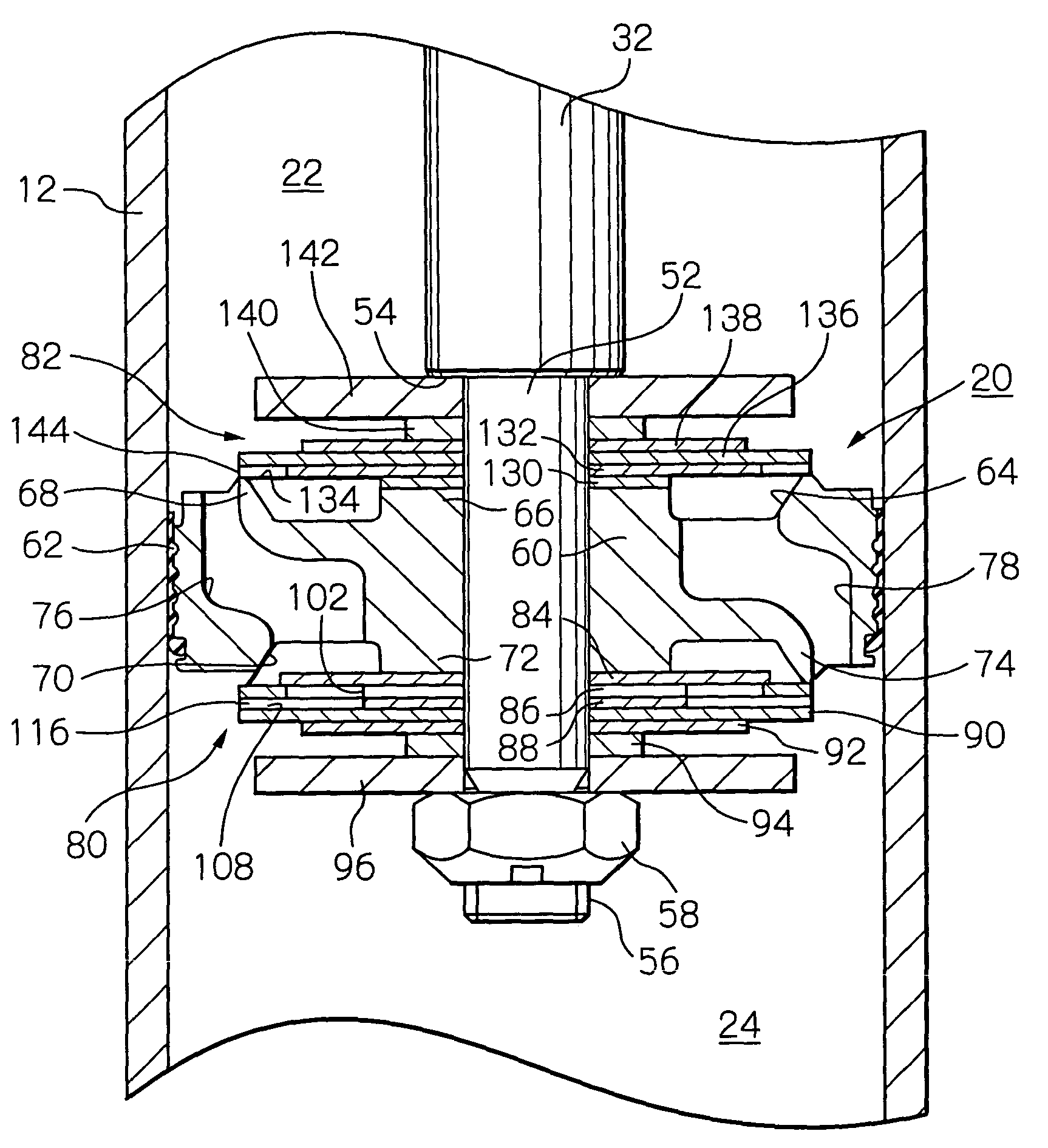
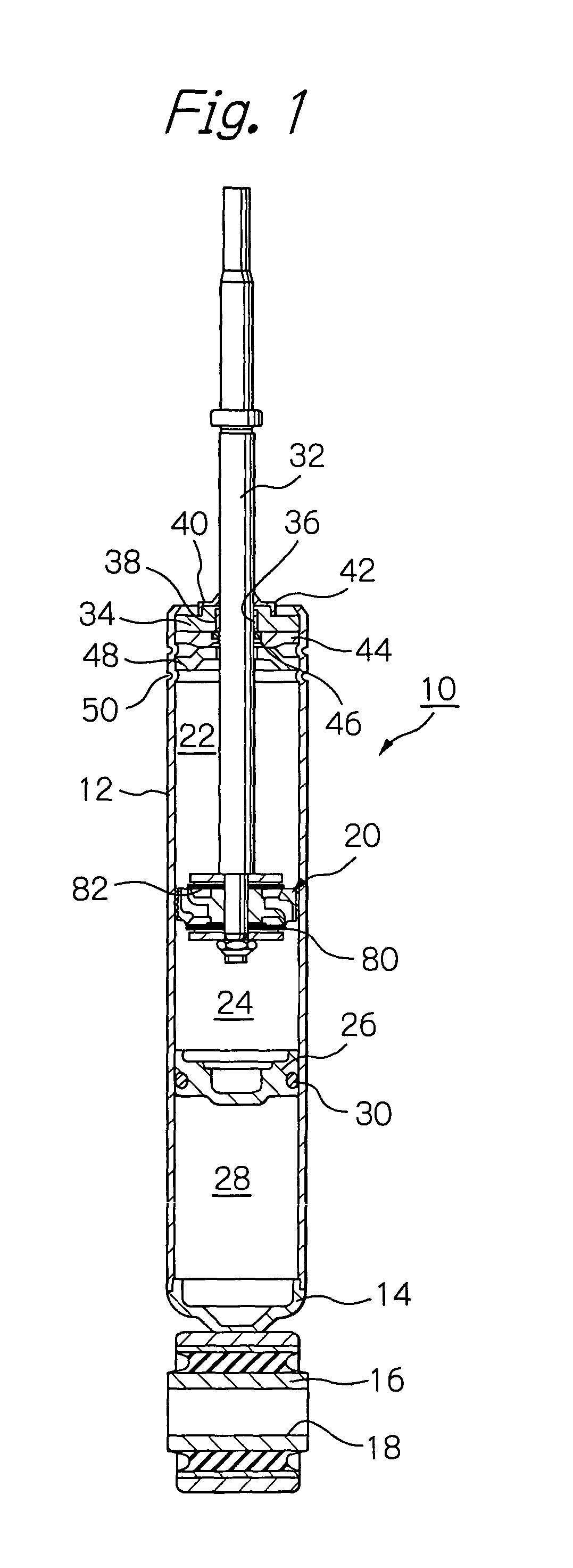
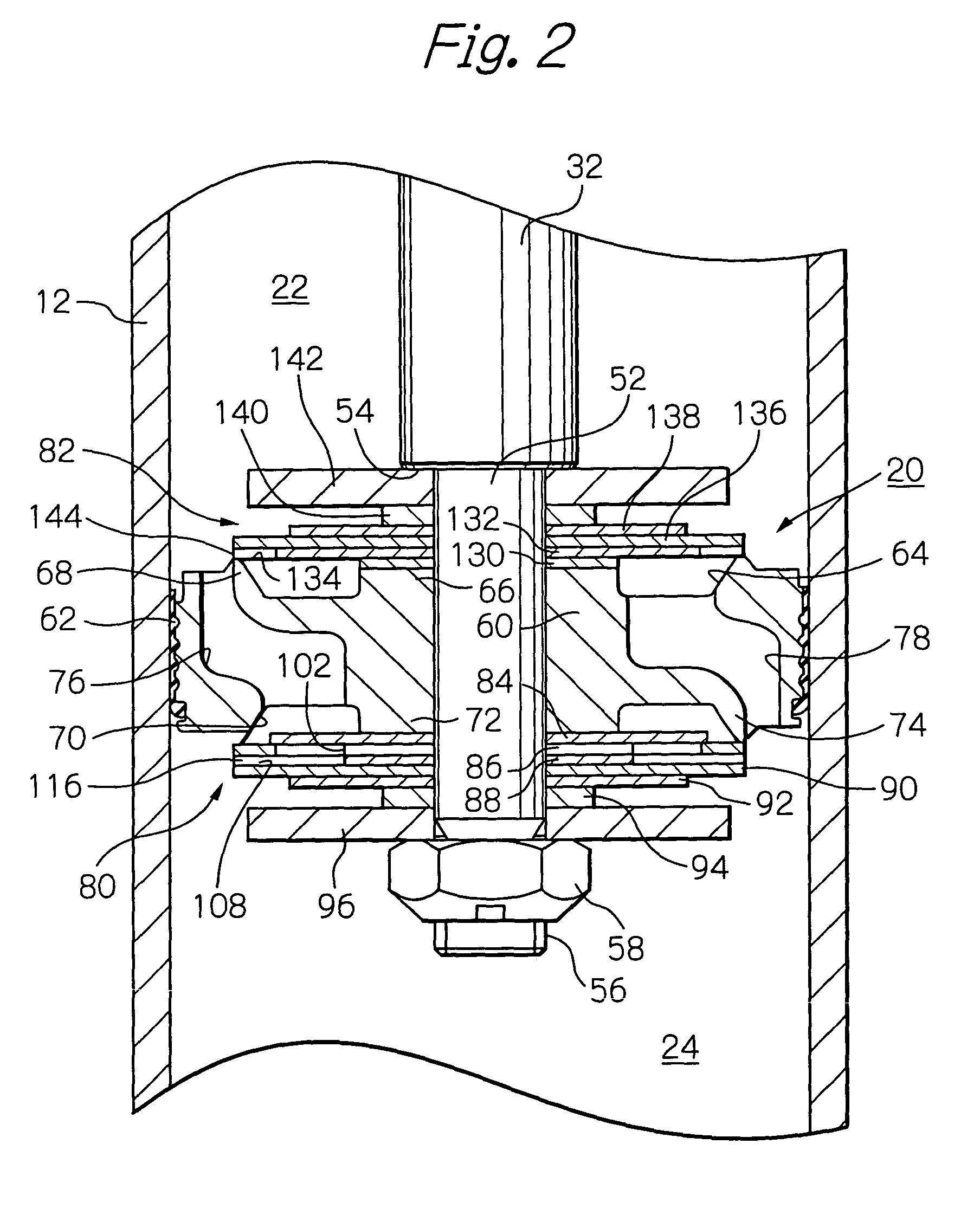
[0029]Referring first to FIG. 1, there is illustrated a hydraulic shock absorber, generally indicated by reference numeral 10, for use in a motor vehicle. The shock absorber 10 includes a cylindrical housing 12 filled with damping fluid. A lower end of the cylindrical housing 12 is closed by a cup-shaped closure member 14. An end mounting 16 is welded or otherwise secured to the closure member 14. The end mounting 16 has a transverse opening 18 for mounting a lower end of the shock absorber 10 on a wheel axle (not shown).

[0030]A piston assembly is generally indicated by reference numeral 20 and slidably disposed within the cylindrical housing 12. The piston assembly 20 divides an interior of the housing 12 into an upper working or rebound chamber 22 and a lower working or compression chamber 24. A free piston 26 is also disposed within the compression chamber 24 to form a gas chamber 28 below the free piston 26. The gas chamber 28 is filled with high pressure gas. An O-ring 30 exten...


PUM


Abstract

A hydraulic shock absorber includes a cylindrical housing within which a piston assembly is slidably received. The piston assembly includes a piston element connected to a piston rod and adapted to divide an interior of the housing into compression and rebound chambers. The piston element has compression and rebound passages to provide fluid communication between the compression and rebound chambers. A valve assembly includes a first valve disc positioned on a lower side of the piston element, and a second valve disc retained on the first valve disc. The second valve disc includes apertures arranged in a circumferentially spaced relationship and are selectively openable and closeable by the first valve disc. A third valve disc is retained on the second valve disc and has notches arranged in a circumferentially spaced relationship. The notches cooperate with the apertures to collectively form ports. The ports are communicated with the compression chamber. A fourth valve disc cooperates with the second valve disc to sandwich the third valve disc so that restrictive orifices are defined in an outer end of the notches. Each of the ports has a cross sectional area greater than that of the restrictive orifices regardless of a relative angular position between the second and third valve discs.

Description

BACKGROUND OF THE INVENTION[0001]The present invention relates to hydraulic shock absorbers for motor vehicles and other vibratory objects and more particularly, to an improved piston assembly for use in a hydraulic shock absorber.[0002]Automotive shock absorbers of the fluid damper type have been in use for many years. Japanese laid-open utility model publication No. 58-94929 discloses a hydraulic shock absorber wherein a valved piston is fit around a piston rod and reciprocatingly received within a cylindrical housing (see FIG. 14). The piston divides an interior of the cylindrical housing into an upper, rebound chamber and a lower, compression chamber. A valve assembly is mounted to a lower surface of a piston head and includes an apertured valve disc (see FIG. 15) normally seated on a valve seat, and a notched valve disc (see FIG. 16) superimposed on the apertured valve disc and adapted to cooperate with the apertured valve disc to collectively form a plurality of ports. An annu...

Claims


Application Information

Patent Timeline
Patent Type & Authority Patents(United States)
IPC IPC(8): F16F9/348F16F9/34
CPCF16F9/348F16F9/3405
Inventor SHINATA, RYO
Owner HITACHI ASTEMO LTD
Why Eureka
Try Eureka