Single beam spray gun positioning system

a positioning system and spray gun technology, applied in the field of spray, can solve the problems of light beam generators involving a certain amount of complexity and expense in manufacture and mounting to spray apparatus, and achieve the effect of simple targeting and positioning system, optimized liquid application, and quick and easy mounting or incorporation

Inactive Publication Date: 2006-05-09
LASER TOUCH & TECH
View PDF14 Cites 23 Cited by
  • Summary
  • Abstract
  • Description
  • Claims
  • Application Information

AI Technical Summary

Benefits of technology

[0004]It is an object of the present invention to provide a simplified targeting and positioning system for a spray apparatus, for use in applying a spray liquid such as a paint or other coating to a surface. It is a further object of the invention to provide such a system which can be quickly and easily mounted to or incorporated in conventional spray-type equipment and which provides a light beam system for positioning the spray apparatus relative to the surface so as to optimize application of the liquid to the surface. It is a further object of the invention to provide such a system which can be quickly and easily engaged with or disengaged from the spray equipment. Yet another object of the invention is to provide such a system which takes advantage of advances in light beam emission technology for providing a low cost, easily adaptable system for positioning a spray apparatus relative to a surface. Yet another object of the invention is to provide such a system which is simple in its components and construction, yet which provides the ability to position the spray pattern on the surface with a relatively high degree of accuracy.

Problems solved by technology

While this type of targeting and positioning system is effective to optimize application of the spray coating, the light beam generator involves a certain amount of complexity and expense in manufacture and in mounting to the spray apparatus.

Method used


Image

  • Single beam spray gun positioning system
  • Single beam spray gun positioning system
  • Single beam spray gun positioning system

Examples


Embodiment Construction

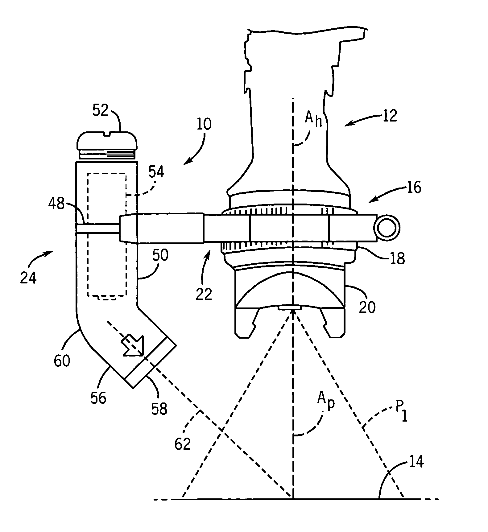
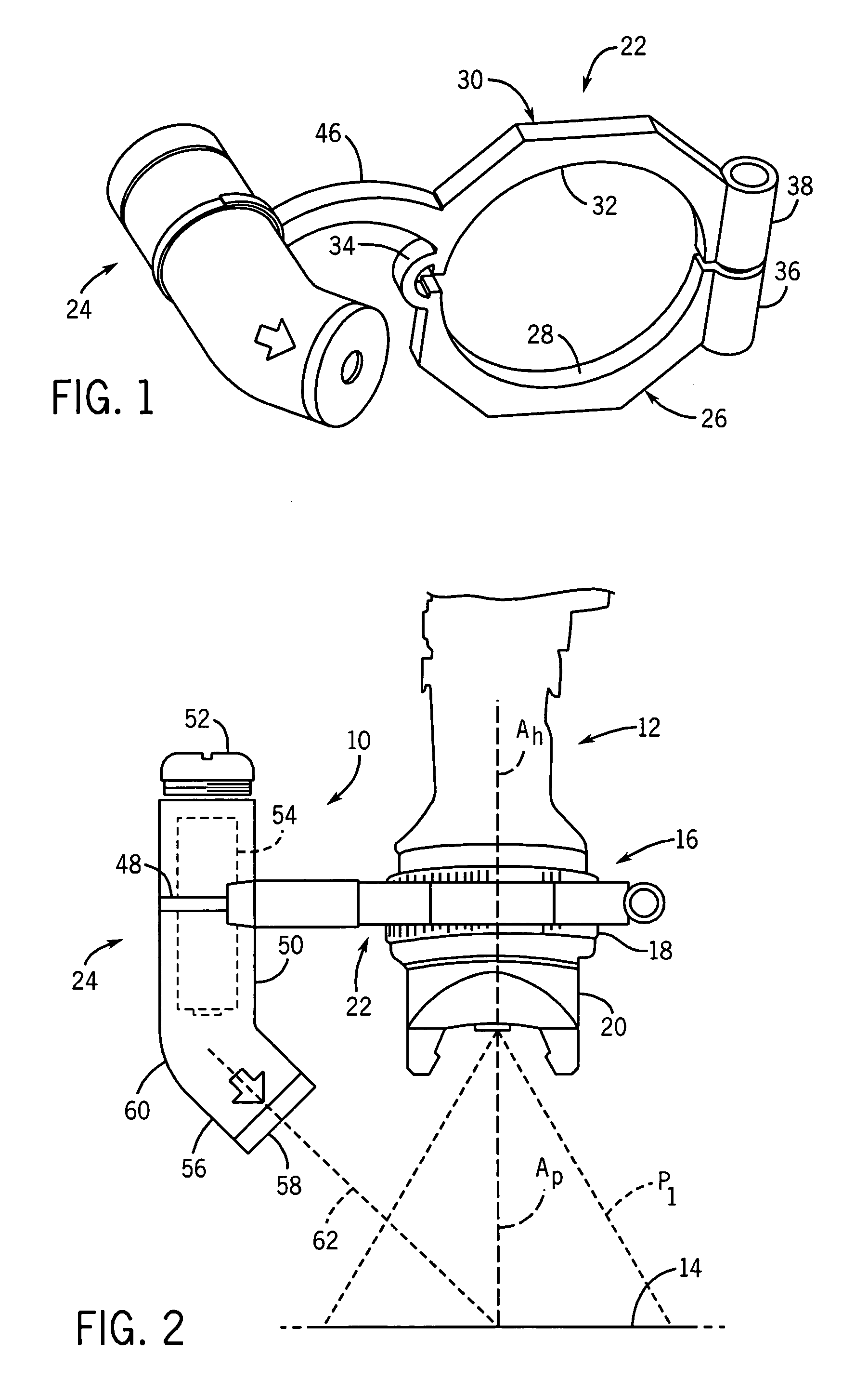
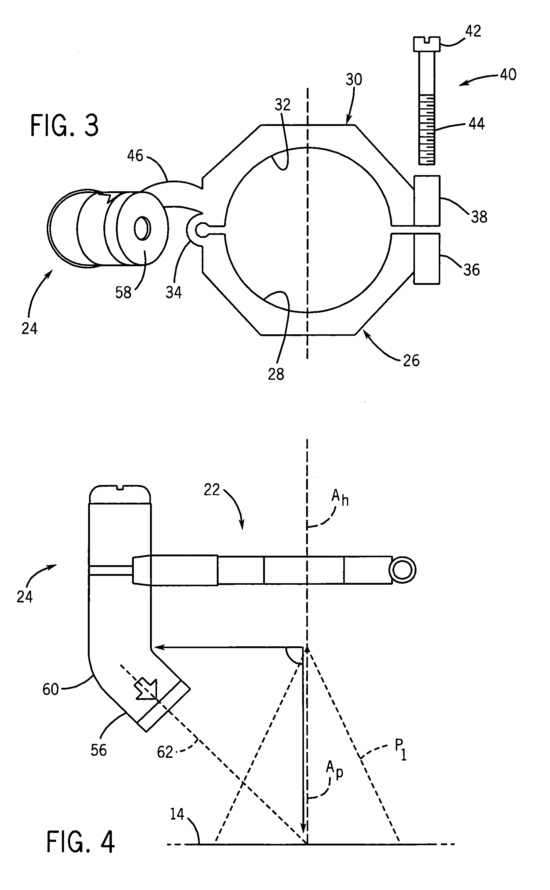
[0024]Referring to FIGS. 1–3, in a first embodiment of the invention, a targeting and positioning system 10 is adapted for use in combination with a spray system. In the illustrated embodiment, targeting and positioning system 10 is shown as being employed in connection with a spray gun 12 forming a part of a spray paint or coating apparatus for applying a spray coating to a surface 14. Spray gun 12 includes a spray head 16 having a ring or collar 18 adapted to secure a spray nozzle 20 to the spray head 16, in a manner as is known.

[0025]Generally, targeting and positioning system 10 includes a mounting arrangement 22 and a light beam generator and emitter 24 secured to mounting arrangement 22.

[0026]Mounting arrangement 22 is in the form of a split ring device adapted for releasable mounting to collar 18 of spray gun 12. Mounting arrangement 22 includes a lower U-shaped section 26 defining an arcuate inner edge 28, and an inverted U-shaped upper section 30 defining an arcuate inner e...


PUM


Abstract

A system for positioning a spray apparatus relative to a surface, in which the spray apparatus directs a liquid coating such as paint toward the surface for applying the liquid to the surface in a spray pattern. A light beam emitter is interconnected with the spray apparatus, and emits a light beam in a predetermined orientation relative to the spray pattern such that the light beam strikes the surface in a center defined by the spray pattern when the spray apparatus is positioned a predetermined distance from the surface. The light beam is oriented such that the distance of the spray apparatus corresponds to a distance providing optimal application of the coating to the surface, to minimize waste and overspray. The light beam emitter may be engaged with the spray apparatus by a releasable mounting arrangement, such that the light beam emitter can be selectively mounted to the spray apparatus. The light beam is emitted from a light beam emitter housing, such as a laser generator. The angle of the light beam relative to the spray pattern can be adjusted so as to vary the distance from the surface at which the light beam coincides with the center of the spray pattern, to provide a gauge for optimal spray application for varying spray parameters.

Description

BACKGROUND AND SUMMARY OF THE INVENTION[0001]This invention relates to spray application of a liquid, such as a paint or other coating, to a surface, and more particularly to a system for targeting and positioning a spray applicator relative to the surface.[0002]In applying a liquid to a surface using a spray gun or other spray applicator, it is advantageous to position the spray applicator in a manner which reduces overspray and minimizes waste spray, so as to provide optimal application of the liquid to the surface. In a spray paint or coating application, this reduces the amount of volatile organic compounds (VOCs) discharged into the air, which is advantageous from an environmental and regulatory compliance standpoint.[0003]Systems have been developed for positioning a spray apparatus relative to a surface or substrate to which the spray liquid is to be applied. Representative systems are shown in Klein, II et al. U.S. Pat. No. 5,598,972 issued Feb. 4, 1997; Klein, II et al. U.S...

Claims


Application Information

Patent Timeline
Patent Type & Authority Patents(United States)
IPC IPC(8): B05B17/00B05B15/00B05D7/02B05B9/01B67D5/08B05B12/12B05B15/68B05D7/00B67D7/00
CPCB05B12/004B05B15/08B05B12/12Y10S239/14B05B12/124B05B15/68
Inventor HORAN, NICHOLAS R.HORAN, CHRISTOPHER M.HORAN, SCOTT J.
Owner LASER TOUCH & TECH
Why Eureka
Try Eureka