

Lightning protection system for a construction, method of creating a lightning protection system and use thereof
- Summary
- Abstract
- Description
- Claims
- Application Information
AI Technical Summary
Benefits of technology
Problems solved by technology
Method used
Image

Examples
Embodiment Construction
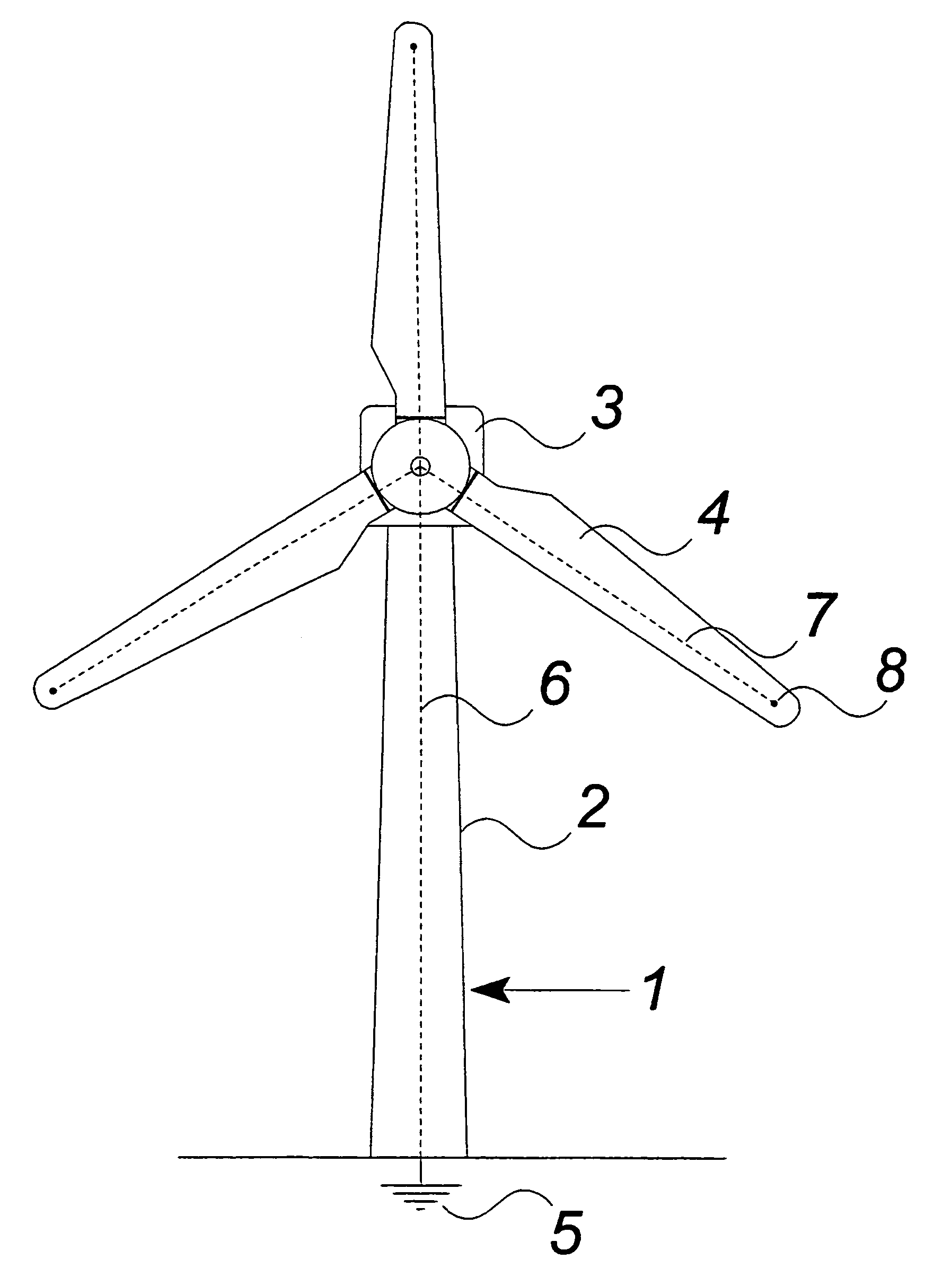
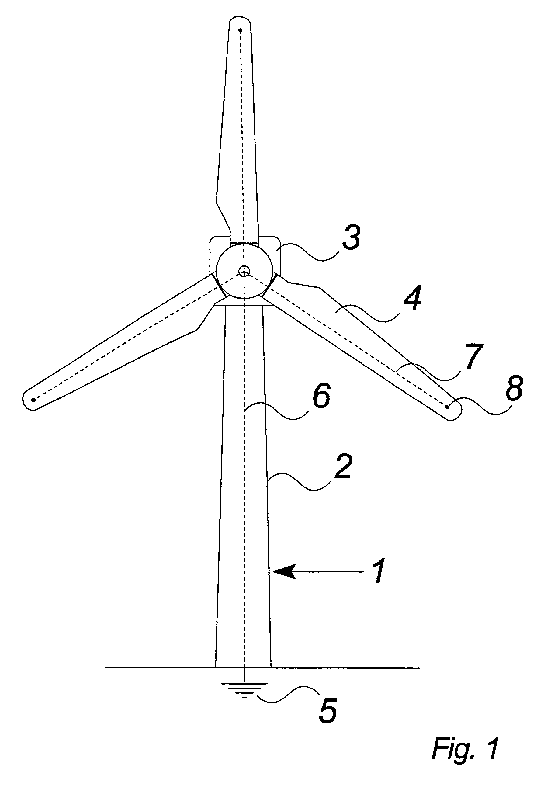
[0054]FIG. 1 shows a standard wind turbine 1 including a tower 2, a nacelle 3 and a rotor with a number of blades 4. The wind turbine further has a lightning conductor in the shape of a connection 6 to a ground plane 5 and the connection extends from the ground plane through the tower and nacelle to the centre of the rotor. From the centre of the rotor the connection extends through the interior of the blades to the tip of the blades. The internal connection is an internal lightning down conductor e.g. in shape of a wire.
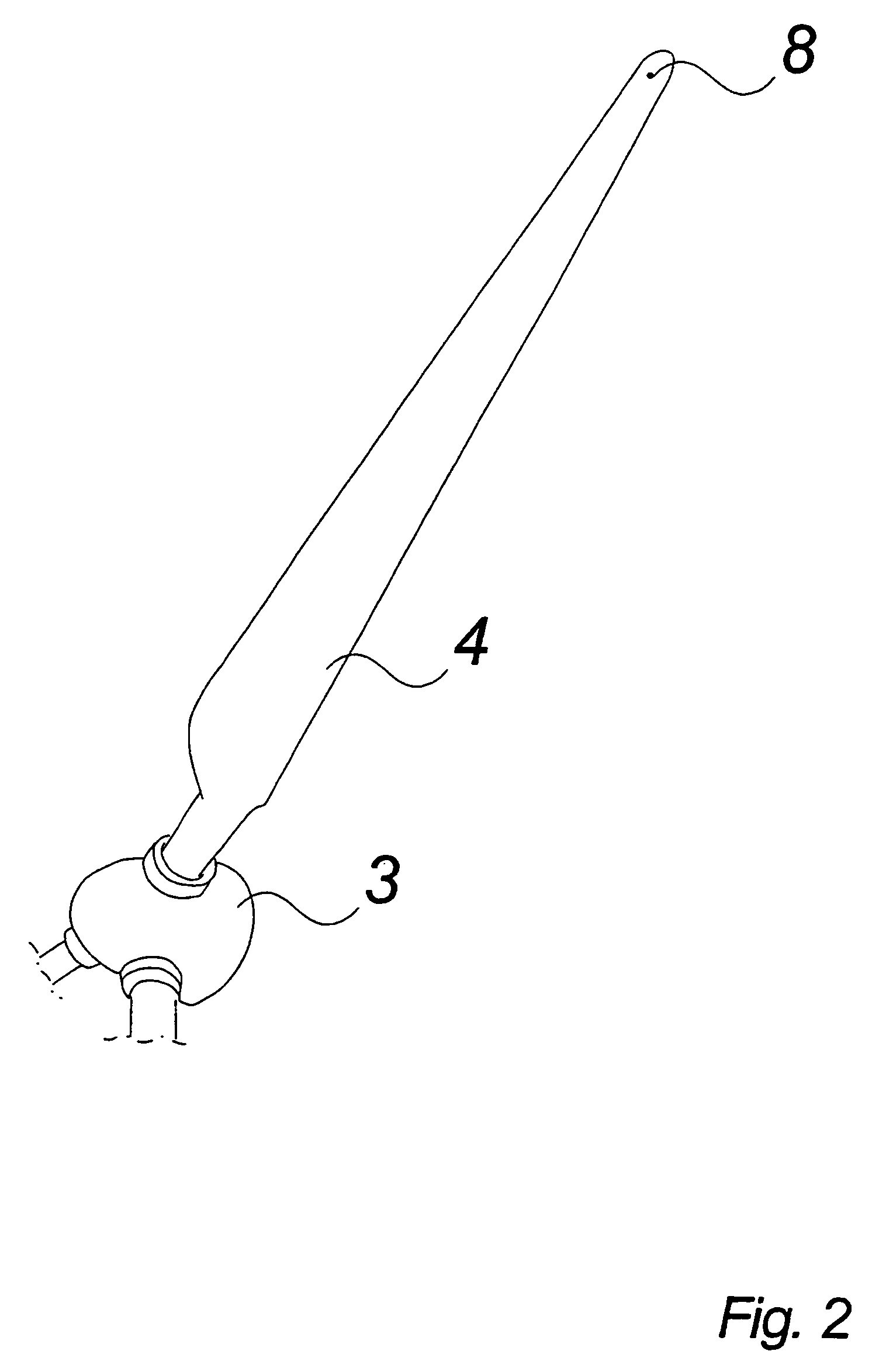
[0055]FIG. 2 shows a section of the rotor and one blade 4 in full length. At the tip of the blade, the penetration point 8 of an internal lightning protection system is shown. Further is the internal lightning protection system shown together with the ground plane and the connection connecting the two.
[0056]FIG. 3 shows a blade with internal lightning conducting means. There are three penetration points 8 on the surface of the blade 4 and the penetration points are ...
PUM
 Abstract
Description
Claims
Application Information