Structure for combining printing circuit board with rack

a printing circuit board and structure technology, applied in the direction of printed circuits, support structure mounting, electrical apparatus casings/cabinets/drawers, etc., can solve the problems of inconvenience and time consumption, etc., to save assembly time and cost, simplify assembly operation, and reduce assembly components

Inactive Publication Date: 2006-05-09
EPO SCI & TECH
View PDF11 Cites 47 Cited by
  • Summary
  • Abstract
  • Description
  • Claims
  • Application Information

AI Technical Summary

Benefits of technology

[0005]For improving a conventional structure for combining a printing circuit board with a rack in order to reduce assembly components, simplify the assembly operation and save the assembly time and cost, the present invention is proposed.
[0006]The main object of the present invention is to provide a structure for combining a printing circuit board with a rack, without using screws and tools to allow the printing circuit board to be combined with the rack more conveniently and be more time consuming.
[0007]Another object of the present invention is to provide a structure for combining a printing circuit board with a rack, without needing to manufacture or purchase assembly components such as screws so that the production, cost can be reduced.

Problems solved by technology

But, a plurality of screws and screw drivers are needed while assembling, it is inconvenient and time consuming.
The structure for fixing a printing circuit board by inserting the bolt sheets into the engaging seats and screwing screws to the locking seats mentioned above not only needs the locking movement of the screws but also needs further to process a mold fabrication to manufacture the bolt sheets and the movement inserting the bolt sheets into the engaging seats; it is assembly time and cost consuming.

Method used


Image

  • Structure for combining printing circuit board with rack
  • Structure for combining printing circuit board with rack
  • Structure for combining printing circuit board with rack

Examples


Embodiment Construction

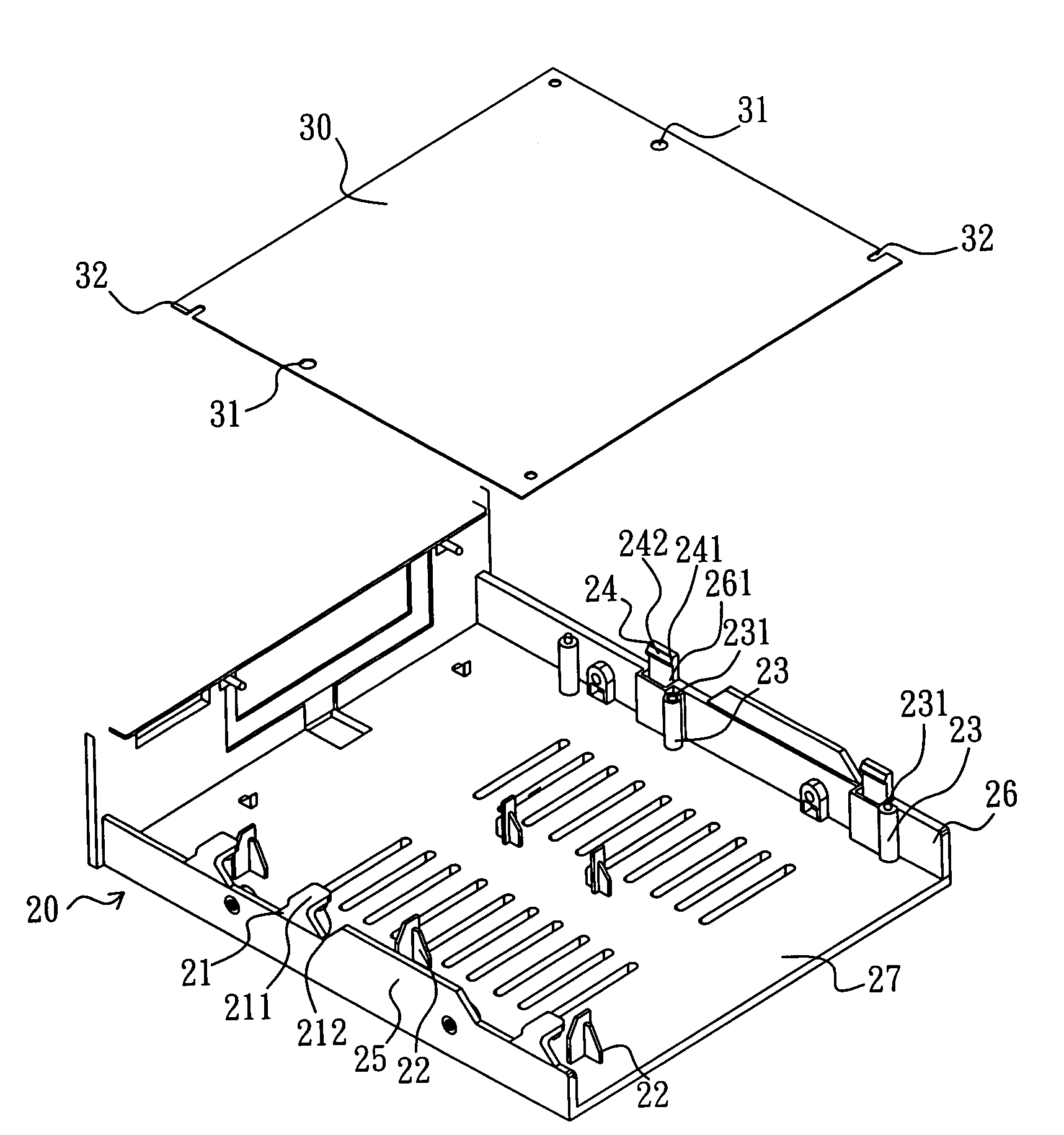
[0013]Please refer to FIG. 2. A structure for combining a printing circuit board with a rack according to the present comprises a rack 20 having at least one fixing sheet 21, a plurality of supporting seats 22, 23 and at least one buckling sheet 24, in which the fixing sheet 21 and the buckling sheet 24 are respectively at two opposite sides of the rack 20 and the supporting seats 22, 23 are disposed between the fixing sheet 21 and buckling sheet 24. In a preferred embodiment of the present invention, the fixing sheet 21 is extended out from the upper end of a first side plate 25 of the rack 20 and has a level section 211 with a positioning pin 212 bended levelly toward the inner side of the rack20 disposed at the lower side thereof. The first side plate 25, the supporting seats 22 and 23, the buckling sheet 24 and a second side plate 26 are all extended upward from a bottom plate 27 of the rack 20. The second side plate 26 is at a side of the rack 20 opposite to the first side plat...


PUM


Abstract

A structure for combining a printing circuit board with a rack comprises a fixing sheet, a plurality of supporting seats and buckling sheet; the fixing sheet and the buckling sheet are respectively at the opposite sides; the fixing sheet has a level section, a positioning pin is disposed at the lower side of the level section; another pin is disposed at the top end of the supporting seat proximate to the buckling sheet; a buckling tenon is disposed on the top end of said buckling sheet; the fixing sheet, the supporting seats and the buckling sheet are used to fix the printing circuit board without needing other screws and screw drivers, the printing circuit board can then be allowed to combine with or separate from the rack. Whereby, the combination or the detaching operation can be more convenient, the production time and cost can be saved.

Description

FIELD OF THE INVENTION[0001]The present invention relates to a structure for combining a printing circuit board with a rack in an electric product such as a computer or optical disk drive.DESCRIPTION OF RELATED ART[0002]Electronic products such as a computer and optical disk drive all have a printing circuit board for providing a circuit structure needed for the electric product. Generally, screws are used to fix the printing circuit board in a rack of the electric product. But, a plurality of screws and screw drivers are needed while assembling, it is inconvenient and time consuming.[0003]Please refer to FIGS. 1A and 1B. Taiwan Patent No. 241,913 discloses a fixture structure for a printing circuit board of a computer mainframe, comprising bolt sheets 11, engaging seats 12, buckling seats 13, supporting seats 14 and locking seats 15. While assembling, install a printing circuit board 19 slantwise into the lower sides of buckling edges 131 of the buckling seats 13, place the printin...

Claims


Application Information

Patent Timeline
Patent Type & Authority Patents(United States)
IPC IPC(8): H01R12/00
CPCH05K7/1404H05K7/1418H05K7/1405
Inventor WANG, HONG-CHUAN
Owner EPO SCI & TECH
Why Eureka
Try Eureka