
Output shaft assembly applied to SHRT unit variable-speed clutch and output shaft arrangement method

An output shaft and clutch technology, applied in mechanical equipment, transmission parts, belts/chains/gears, etc., can solve the problems of large motor capacity, low operation rate, large gap, etc., to reduce assembly components, simplify structure, structure compact effect

Pending Publication Date: 2019-06-07
HARBIN GUANGHAN POWER TRANSMISSION
View PDF9 Cites 0 Cited by
  • Summary
  • Abstract
  • Description
  • Claims
  • Application Information

AI Technical Summary

Problems solved by technology

Due to the low operating rate of some auxiliary equipment in sintering production and the selected motor capacity is too large, the power consumption of the main exhaust fan accounts for 50%-70%
At the same time, the utilization rate of waste heat in the sintering process in my country is less than 30%, which is very different from developed countries, and the average energy consumption per ton of sinter is 20kgce higher.

Method used


Image

  • Output shaft assembly applied to SHRT unit variable-speed clutch and output shaft arrangement method
  • Output shaft assembly applied to SHRT unit variable-speed clutch and output shaft arrangement method

Examples


Embodiment 1

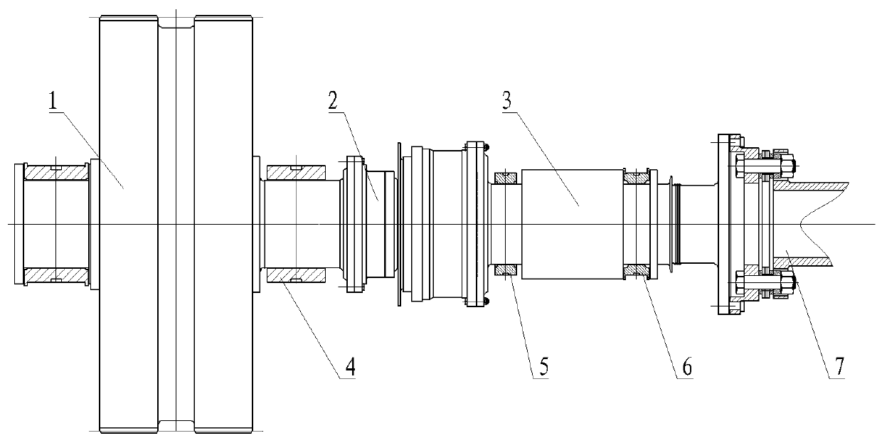
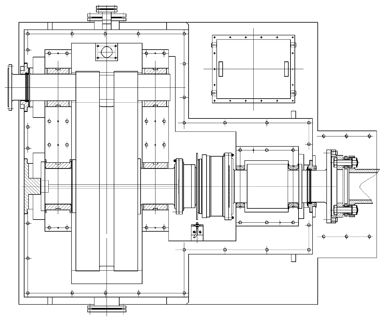
[0015] refer to figure 1 and figure 2 , an output shaft assembly applied to the transmission clutch of the SHRT unit, including a gear shaft 1, a synchronous automatic clutch 2, an output shaft 3, a gear shaft sliding bearing 4, an output shaft front bearing 5, an output shaft rear bearing 6 and a coupling 7 The gear shaft 1 is connected with the synchronous automatic clutch 2, the gear shaft 1 is supported by the gear shaft sliding bearing 4 double points, the other end of the synchronous automatic clutch 2 is connected with the output shaft 3, and the output shaft 3 is connected by the output shaft front bearing 5 and the output shaft rear bearing 6 Two-point support, in which the front bearing 5 of the output shaft is a supporting sliding bearing, and the rear bearing 6 of the output shaft is a thrust bearing, which cooperates with the thrust surface structure on the output shaft 3 to achieve the functions of positioning and bearing external axial force. The balance plate...

Embodiment 2

[0017] An output shaft arrangement method applied to the output shaft assembly of the variable speed clutch of the SHRT unit, the output shaft of the output shaft assembly adopts the arrangement form of double fulcrums, and the system stability is enhanced by adding a counterweight plate and matching sliding bearings, The output shaft is a rigid shaft, one end of which is rigidly connected to the output assembly of the synchronous automatic clutch, the input assembly of the synchronous automatic clutch is rigidly connected to the gear shaft, and the other end is rigidly connected to the elastic coupling, and the output shaft is supported by two sliding bearings with a span , one of the sliding bearings is a support bearing, the other is a thrust bearing, and the gear shaft connected with the synchronous automatic clutch is supported by two sliding bearings. The arrangement of double fulcrums and elastic links at both ends has higher stability and reliability. At the same time, ...

Embodiment 3

[0019] The output shaft arrangement method of the second embodiment applied to the output shaft assembly of the variable speed clutch of the SHRT unit is also applied to the variable speed clutches of the BPRT unit and the steam-electric dual-drive induced draft unit.


PUM


Abstract

The invention belongs to the technical field of variable-speed clutches, and particularly relates to an output shaft assembly applied to an SHRT unit variable-speed clutch and an output shaft arrangement method. The output shaft assembly applied to the SHRT unit variable-speed clutch comprises a gear shaft, a synchronous automatic clutch, an output shaft, a gear shaft sliding bearing, an output shaft front bearing, an output shaft rear bearing and a coupling, wherein the gear shaft is connected with the synchronous automatic clutch, the gear shaft is supported by the gear shaft sliding bearingin a two-point mode, the other end of the synchronous automatic clutch is connected with the output shaft, the output shaft is supported by the output shaft front bearing and the output shaft rear bearing in a two-point mode, the output shaft front bearing is a supporting sliding bearing, the output shaft rear bearing is a thrust bearing, a thrust surface structure on the output shaft is combinedto achieve the functions of positioning and outside axial force bearing, the output shaft adopts a counterweight disk structure between the two bearings, and the other end of the output shaft is connected with the coupling. The gear shaft sliding bearing, the output shaft front bearing and the output shaft rear bearing are all assembled on a box body. The output shaft assembly has the advantagesthat supporting is stable, the structure is compact, and the system stability is improved.

Description

Technical field: [0001] The invention belongs to the technical field of transmission clutches, and in particular relates to an output shaft assembly and an output shaft arrangement method applied to the transmission clutch of a SHRT unit. Background technique: [0002] The energy consumption of the sintering process of the metallurgical process accounts for more than 10% of the energy consumption per ton of steel. The heat energy taken away by the waste gas discharged from the cooler is about 35% of the heat consumption of the sintering system of the sintering process. The energy consumption of the sintering process accounts for about Metallurgy accounts for 12% of the total energy consumption, which is the second largest energy-consuming process after ironmaking. In the sintering process of iron and steel enterprises, the capacity of the sintering main exhaust fan accounts for 30%-50% of the total installed capacity. Due to the low operating rate of some auxiliary equipmen...

Claims


Application Information

Patent Timeline
Patent Type & Authority Applications(China)
IPC IPC(8): F16H57/00F16H57/023
Inventor 黄莹莹韩莹莹艾红旭赵天宇周金阳
Owner HARBIN GUANGHAN POWER TRANSMISSION
Learn More