Hydroelectric generator

a technology of hydroelectric generators and generators, which is applied in the direction of electric generator control, rotors, vessel construction, etc., can solve the problems of not being able to adapt to multiple generating devices or to rotate both elements of a generation device with respect to the shell

Inactive Publication Date: 2006-05-09
AUKON DENNIS W
View PDF17 Cites 31 Cited by
  • Summary
  • Abstract
  • Description
  • Claims
  • Application Information

AI Technical Summary

Problems solved by technology

The gearing system disclosed by Wilmore does not provide rotational forces in more than one direction to multiple generator units.
As with Wilmore, however, the gearing system disclosed by McGee, as well as the gearing system in other hydroelectric generators, is not adaptable to accommodate multiple generating devices or to rotate both elements of a generation device with respect to the shell.

Method used


Image

  • Hydroelectric generator
  • Hydroelectric generator
  • Hydroelectric generator

Examples


Embodiment Construction

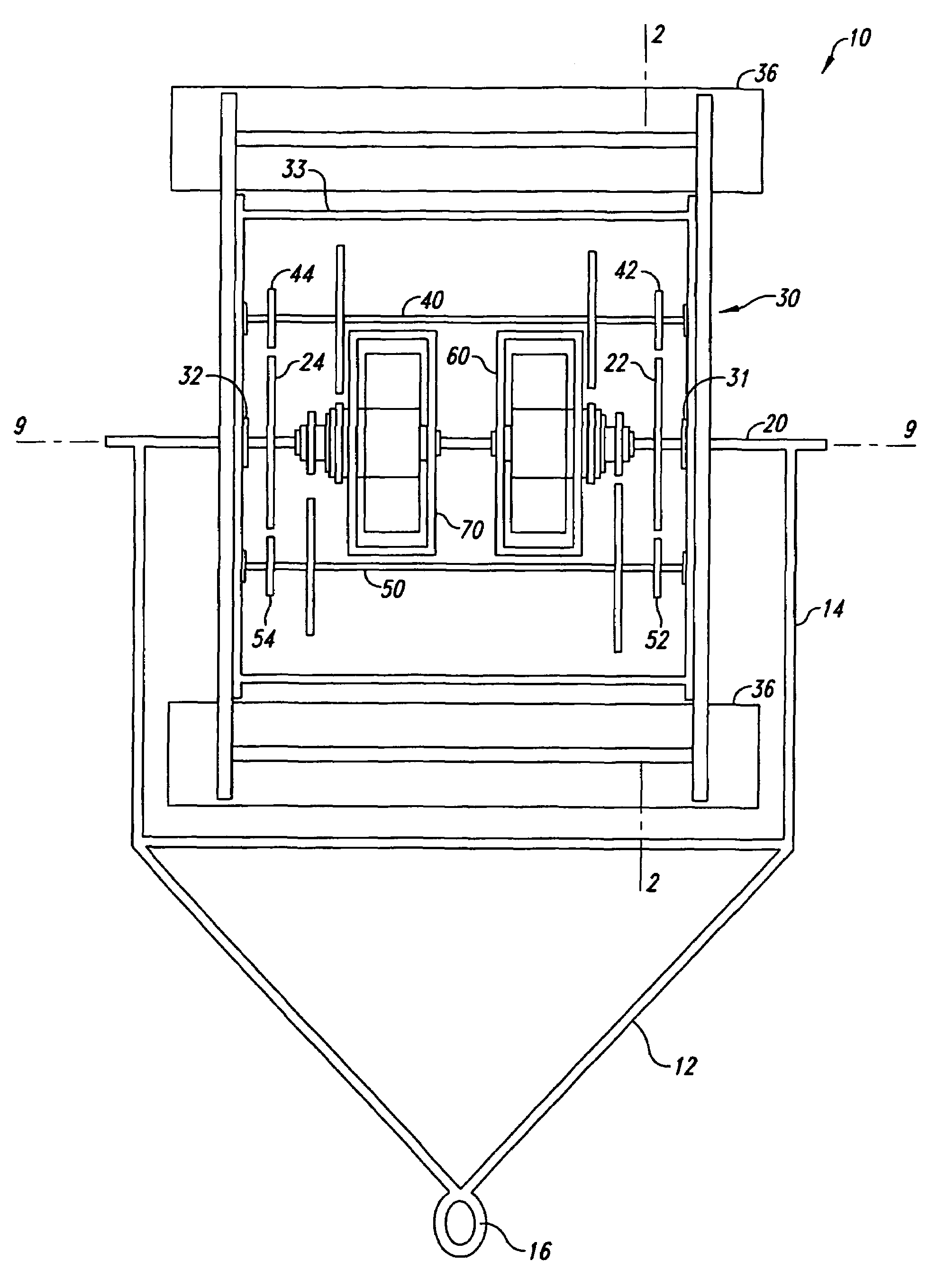
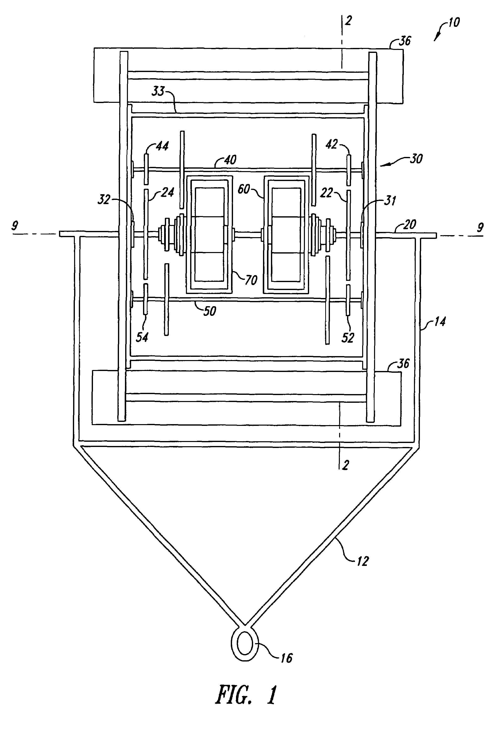
[0021]The present invention provides for a hydroelectric generator having an efficient transmission system that can be adopted for use with a variety of sources of moving water. Embodiments of the invention will be described using a limited number of representative examples and drawings.

[0022]Referring now to FIGS. 1–3, a support 12 secures the hydroelectric generator 10 to the earth (not shown) or to a structure (not shown). As shown more clearly in FIG. 1, the support 12 has a yoke 14 and a mount 16. The mount 16 secures the support to the earth (not shown) or to a structure (not shown). One of skill in the art will recognize that alternative supports may be used. For example, cables attached to the river bottom or to the river bank could be employed. Alternatively, two poles anchored to the bottom of a body of water could be employed. The support could be formed of two anchors holding the hydroelectric generator in position in a waterfall. In FIGS. 1–3, a central axle 20 is rigid...


PUM


Abstract

A hydroelectric generator having a fixed axle, at least one transmission axle parallel to the fixed axle, and a transmission system configured to rotate the transmission axle about the fixed axle and to apply a force to at least one driven member of a device for generating electricity.

Description

BACKGROUND OF THE INVENTION[0001]1. Field of the Invention[0002]The present invention is directed to a hydroelectric generator, and more particularly, to a hydroelectric generator utilizing an efficient transmission system within a rotatable drum impelled by water.[0003]2. Description of the Related Art[0004]Hydroelectric generators use the force of moving water to generate electrical energy. Typically, moving water drives a transmission system that in turn drives a device to generate electricity, such as a direct current electrical generator or an alternator.[0005]An example of a known hydroelectric generator is disclosed in U.S. Pat. No. 833,361, issued to Wilmore (“Wilmore”). Wilmore includes a frame that is supported by chains attached to posts. A rotary casing is mounted on the frame. Waves or river currents or flowing streams impact on the casing to spin the casing around three fixed shafts contained within the casing. As the casing spins in one direction, gearing attached to ...

Claims


Application Information

Patent Timeline
Patent Type & Authority Patents(United States)
IPC IPC(8): F03B13/00F03B13/10H02K7/18H02P9/00H02P9/04
CPCH02P9/00H02K7/1823
Inventor AUKON, DENNIS W.
Owner AUKON DENNIS W
Why Eureka
Try Eureka