

Differential signal receiving device and differential signal transmission system
- Summary
- Abstract
- Description
- Claims
- Application Information
AI Technical Summary
Benefits of technology
Problems solved by technology
Method used
Image

Examples
Embodiment Construction
[0029]A specific embodiment of the present invention will be explained hereinafter with reference to the drawings.
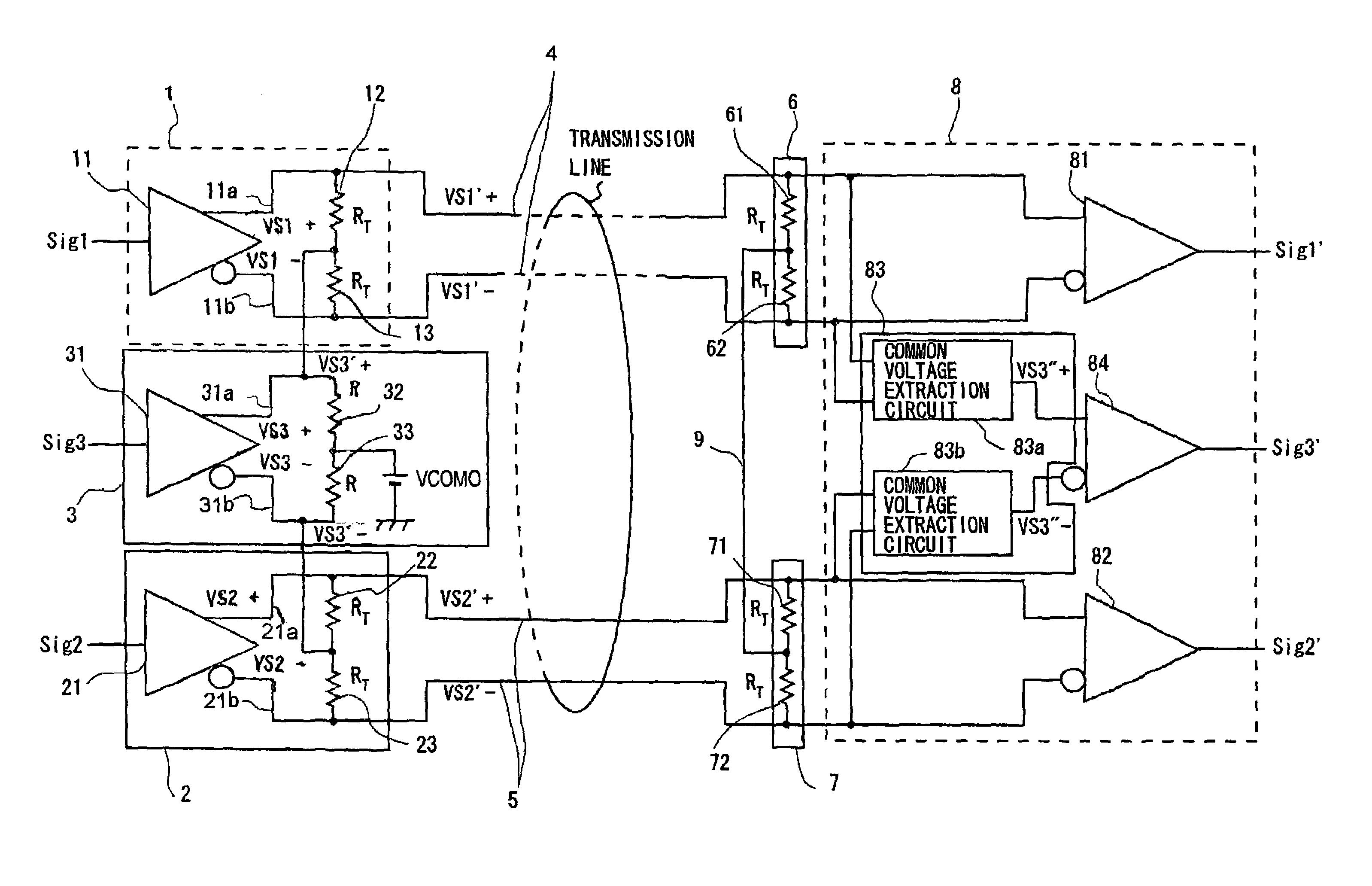
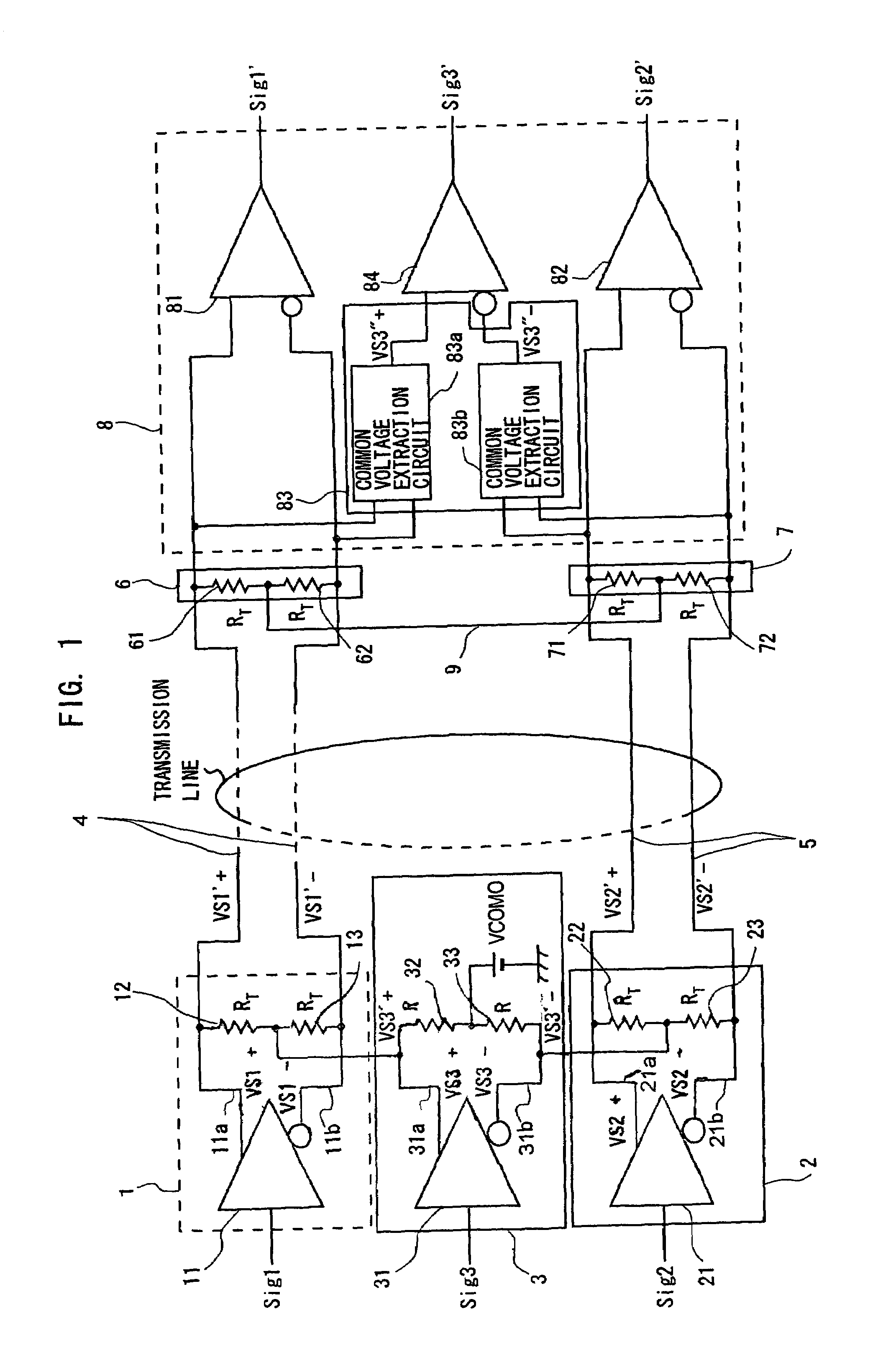
[0030]Referring first to FIG. 1, a block circuit diagram of a differential signal transmission system according to a specific embodiment of the invention is shown.
[0031]The differential signal transmission system shown in FIG. 1 includes a first output buffer 1, a second output buffer 2, a third output buffer 3, a signal line pair 4, a signal line pair 5, a first terminator 6, a second terminator 7, and an input buffer 8.
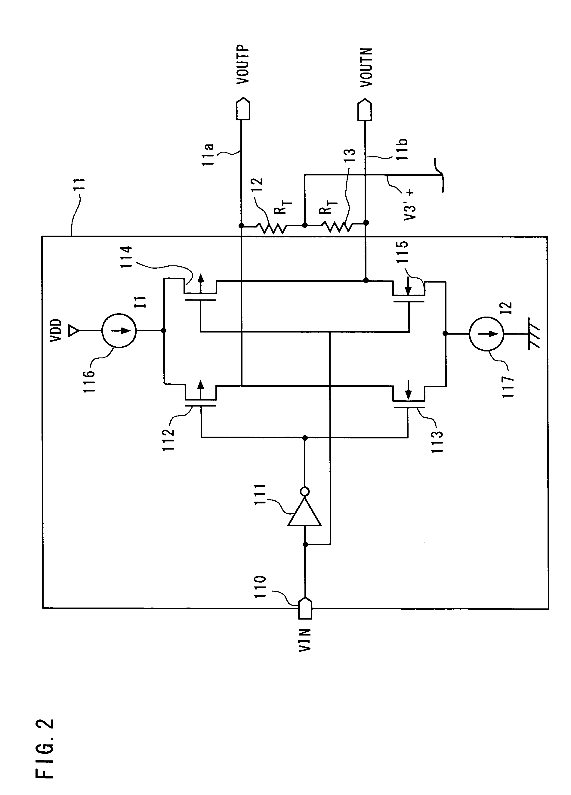
[0032]The first output buffer 1, which is an example of a first transmission circuit, includes a differential signal output circuit 11 and resistors 12 and 13.
[0033]The differential signal output circuit 11 outputs a first differential signal (VS1+ and VS1−) corresponding to an input signal Sig1 to the pair of signal lines 4 through a pair of output lines 11a and 11b of the differential signal output circuit 11. Specifically, the differential signal outp...
PUM
 Abstract
Description
Claims
Application Information