
Method and device for accurately pointing a satellite earth station antenna

Active Publication Date: 2006-08-17
VIASAT INC
View PDF6 Cites 27 Cited by
  • Summary
  • Abstract
  • Description
  • Claims
  • Application Information

AI Technical Summary

Benefits of technology

[0005] Particular embodiments of the present invention provide an improved device and techniques for accurately pointing a satellite Earth station antenna, especially in satellite systems employing antenna beam frequency reuse.
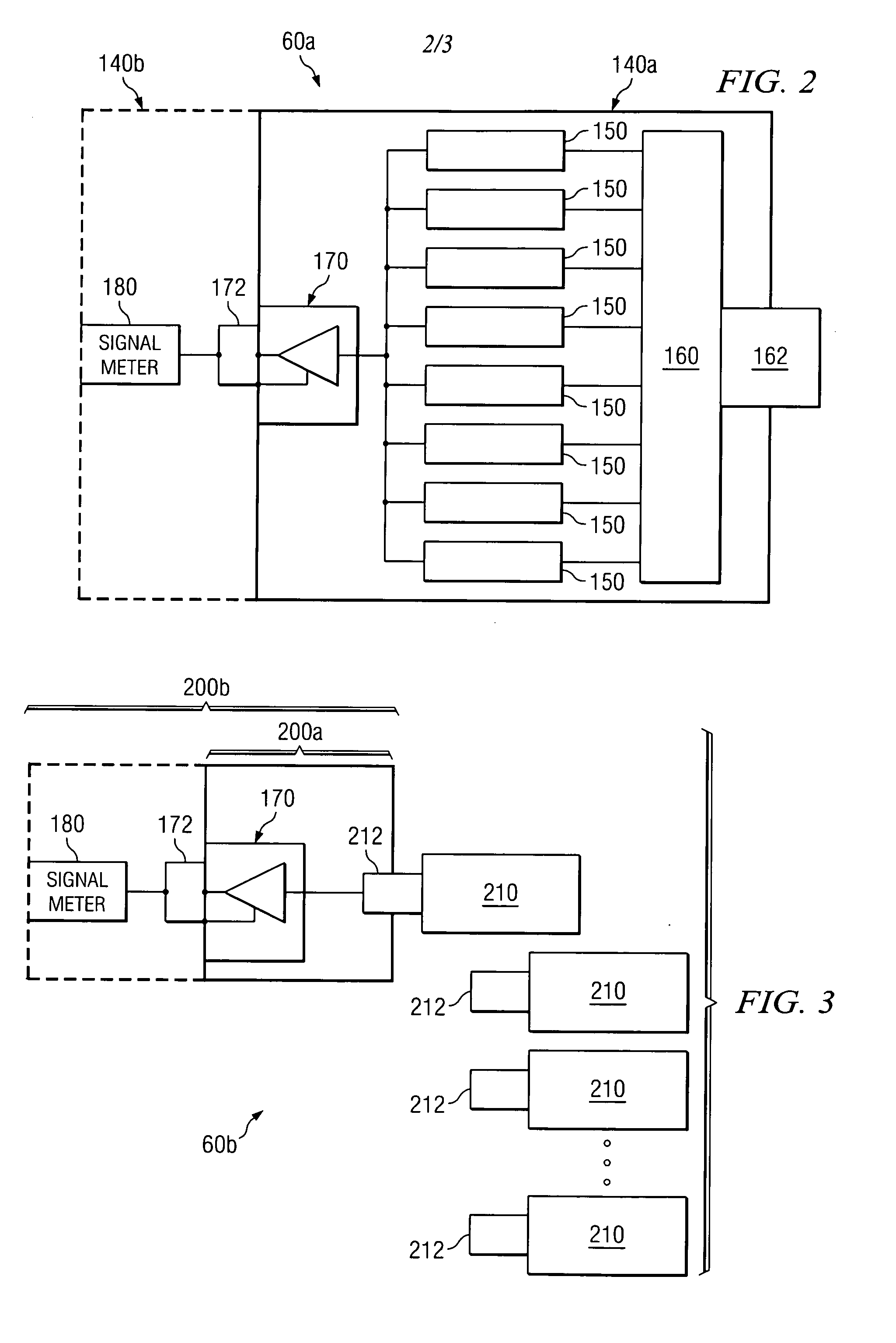
[0007] The method also includes constructing a device or devices that attach directly or indirectly to a satellite antenna pointing meter, such device or devices consisting of a plurality of filters associated with various geographic locations and a switch or other method of allowing the installer to select the appropriate filter based on the location of the Earth station antenna.
[0009] In accordance with another embodiment of the present invention, a device for allowing installers to accurately point Earth station antennas in a satellite system incorporating spot beam frequency reuse consists of a coaxial input port, a plurality of electronic filters, a filter selector to choose one or a combination of the electronic filters, a signal amplifier, and a coaxial output port. Each filter or filter combination is associated with a particular geographic area with the filter characteristics optimized to the satellite signals of interest in that geographic area and designed to effectively block noise and any interfering signals that may be present. The filter selector is capable of selectively connecting the signal amplifier to an output of one or more of the filters and the signal amplifier is capable of amplifying the output of one or more of the filters. Additionally, the output port, which may be attached to a power sensor or antenna pointing meter, provides a signal level that is highly sensitive to the power of the desired satellite signal and therefore highly sensitive to antenna pointing error.
[0011] One or more technical advantages of the present invention may be readily apparent to one skilled in the art from the following figures, descriptions, and claims. Technical advantages of certain embodiments of the present invention include providing an inexpensive and portable solution for isolating and measuring the strength or other signal quality measure of satellite signals to accurately point Earth station antennas in systems where the frequency bands and characteristics of the satellite signals are not uniform over the coverage area. In one embodiment for example, a commonly available antenna pointing meter may be fitted with an inexpensive adapter and used to accurately point an Earth station antenna in a system employing antenna beam frequency reuse that may otherwise require a custom-built and more expensive antenna pointing device. Other technical advantages of certain embodiments of the present invention include providing a flexible system for measuring satellite signals that can be easily updated or reconfigured to adjust to changes in the overall system. While specific advantages have been enumerated above, various embodiments may include all, some, or none of the enumerated advantages.

Problems solved by technology

Such pointing meters may not be effective in a satellite system incorporating antenna beam frequency reuse since the signal radiated toward a specific location may be in a single channel or frequency band.
Since background noise power is essentially independent of user Earth station antenna orientation, an antenna pointing meter used in this manner is desensitized by noise and is not an effective indicator of maximum signal power from the satellite.

Method used


Image

  • Method and device for accurately pointing a satellite earth station antenna
  • Method and device for accurately pointing a satellite earth station antenna
  • Method and device for accurately pointing a satellite earth station antenna

Examples


Embodiment Construction

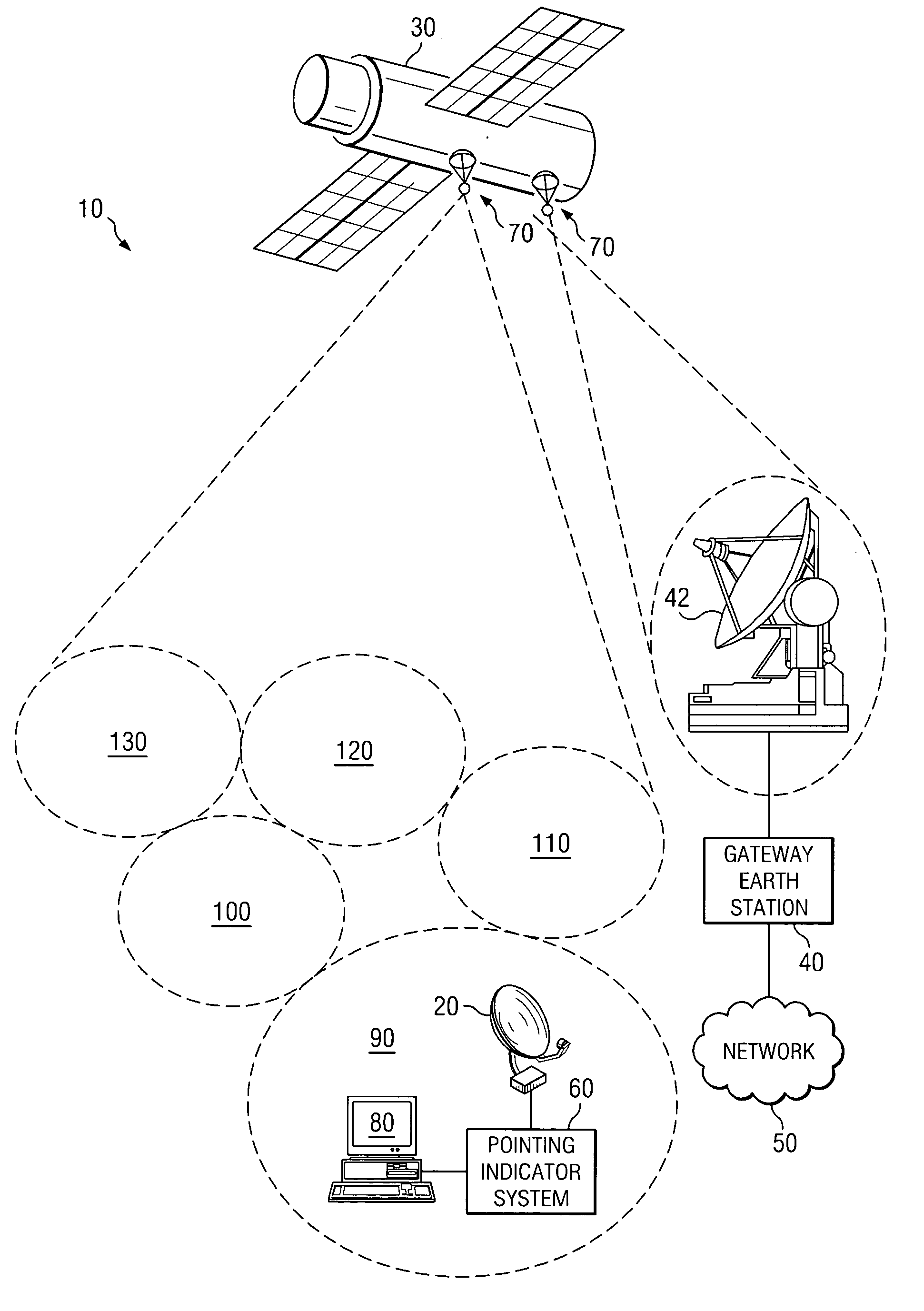
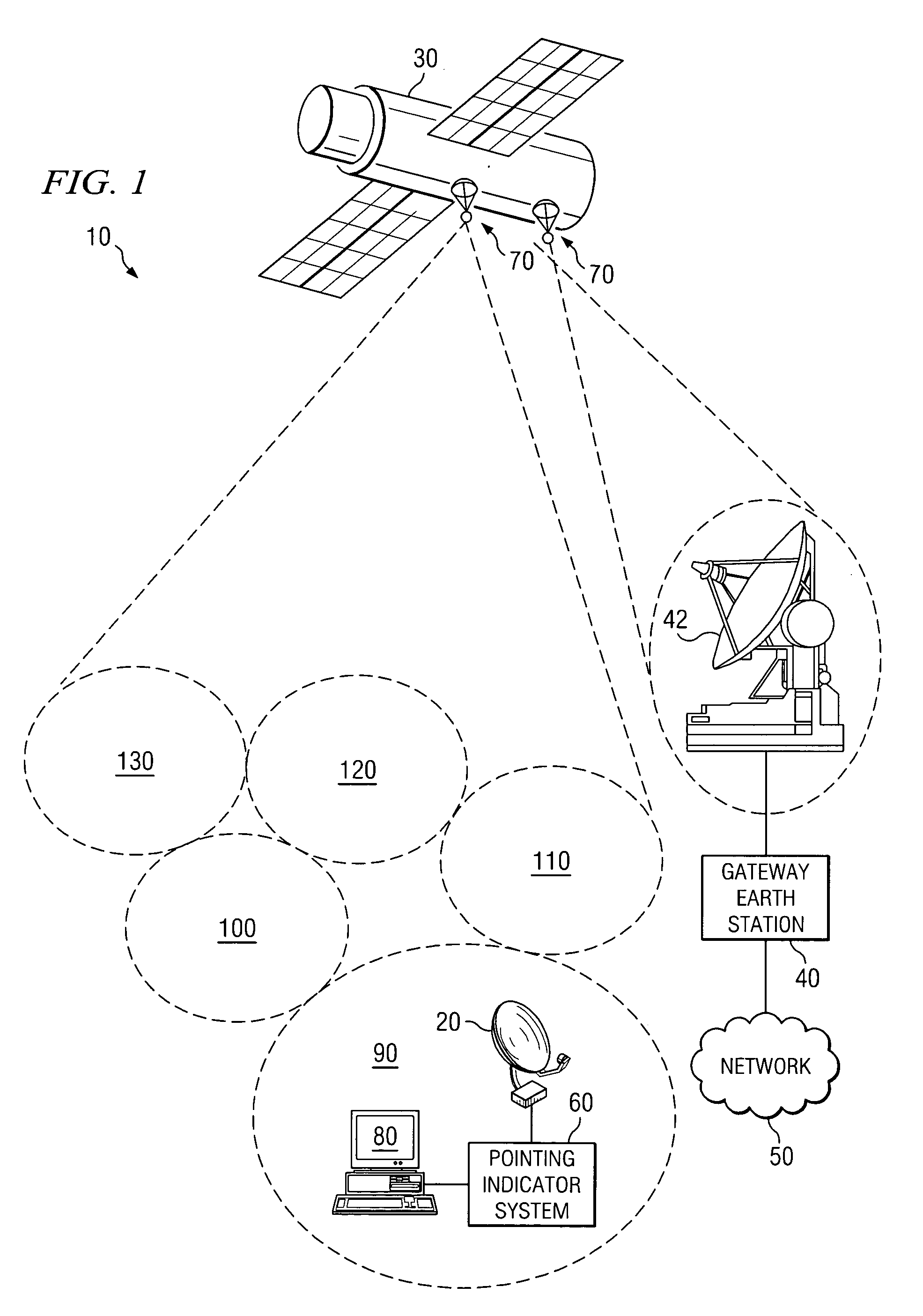
[0016]FIG. 1 illustrates an example communication system 10 that provides voice and / or data communication to a communication device 80 through satellite antennas 70. As illustrated, communication system 10 includes a user Earth station antenna 20, a satellite or satellites 30, a gateway Earth station 40, a network 50, an antenna pointing indicator system 60, and a user communication device 80. Satellite antennas 70 may form a plurality of overlapping and / or non-overlapping beams on the earth, depicted as satellite antenna beams and corresponding geographic coverage areas 90, 100, 110, 120 and 130. A user may utilize user Earth station antenna 20, depicted in satellite antenna beam 90 for purposes of illustration, to communicate with gateway Earth station 40 through one or more satellites 30 for the purpose of accessing network 50. During installation and / or operation, antenna pointing indicator system 60, according to a particular embodiment of the present invention, may be used to ...


PUM


Abstract

A device for measuring the received signal strength at an Earth station antenna has the capability to provide an accurate pointing indication when the frequency bands and other key characteristics of the satellite signals are not uniform over the coverage area. The device has an input port, a plurality of passive or active signal filters, a filter selector and an output port. The device may further contain a signal amplifier with automatic or manual gain control. A plurality of filters is provided which may be coupled singularly or in combination between the input port and the output port. Each filter or combination of filters is associated with a particular geographic area and capable of allowing the satellite signal assigned to that geographic area to pass while attenuating or blocking other signals, noise and interference. The filter selector is used to connect the appropriate filter or combination of filters between the input port and the output port. A signal amplifier with manual or automatic gain control may be included to provide an output signal at the desired signal level. The output port may be connected to a power measuring unit, antenna pointing meter or other similar device to provide an accurate antenna pointing indication in the particular geographic area corresponding to the filter or filter combination selected.

Description

TECHNICAL FIELD [0001] This invention relates in general to wireless communication systems, and more particularly to accurately pointing a satellite Earth station antenna based on the strength of the signal received in a satellite communication system. BACKGROUND [0002] With the rapid growth in communication usage in recent years and the high cost of adding landline infrastructure, satellite systems have become an increasingly common solution for providing data and voice communication. Satellite links, either one-way or two-way, may be used for communication between a satellite and a population of user Earth station terminals. These user Earth station terminals may each include an Earth station antenna and various transmit and receive equipment appropriate for communicating with the satellite. These user Earth station terminals may be clustered in a single urban or rural area or may be widely installed over large geography, which may include entire continents and ocean regions. Such...

Claims


Application Information

Patent Timeline
IPC IPC(8): H01Q3/00
CPCH01Q1/1257H01Q3/08
Inventor HUDSON, ERWIN C.MARTIN, REMBERTO L.
Owner VIASAT INC
Learn More