Acoustic correction apparatus

a correction apparatus and acoustic technology, applied in the direction of electrical transducers, transducer details, stereophonic arrangments, etc., can solve the problems of adversely affecting the sound image perceived by the listener, and achieve the effect of improving the stereo image, realizing and directing the sound experience for the listener

Inactive Publication Date: 2006-05-09
DTS
View PDF88 Cites 47 Cited by
  • Summary
  • Abstract
  • Description
  • Claims
  • Application Information

AI Technical Summary

Benefits of technology

[0017]The acoustic correction apparatus as disclosed herein, and the associated methods of operation, provide a sophisticated and effective system for improving a sound image in an imperfect reproduction environment.
[0048]In another embodiment, the corrected audio signal is a stereophonic signal comprising a difference signal representing the amount of stereo information present in the corrected audio signal, the acoustic-image enhancement circuit equalizing the difference signal to emphasize reverberant sound energy in the corrected audio signal for broadening the apparent stereo image.

Problems solved by technology

Within an audio reproduction environment, speakers may be placed at a location remote from a listener's ears thereby adversely affecting a sound image perceived by the listener.

Method used


Image

  • Acoustic correction apparatus
  • Acoustic correction apparatus
  • Acoustic correction apparatus

Examples


Embodiment Construction

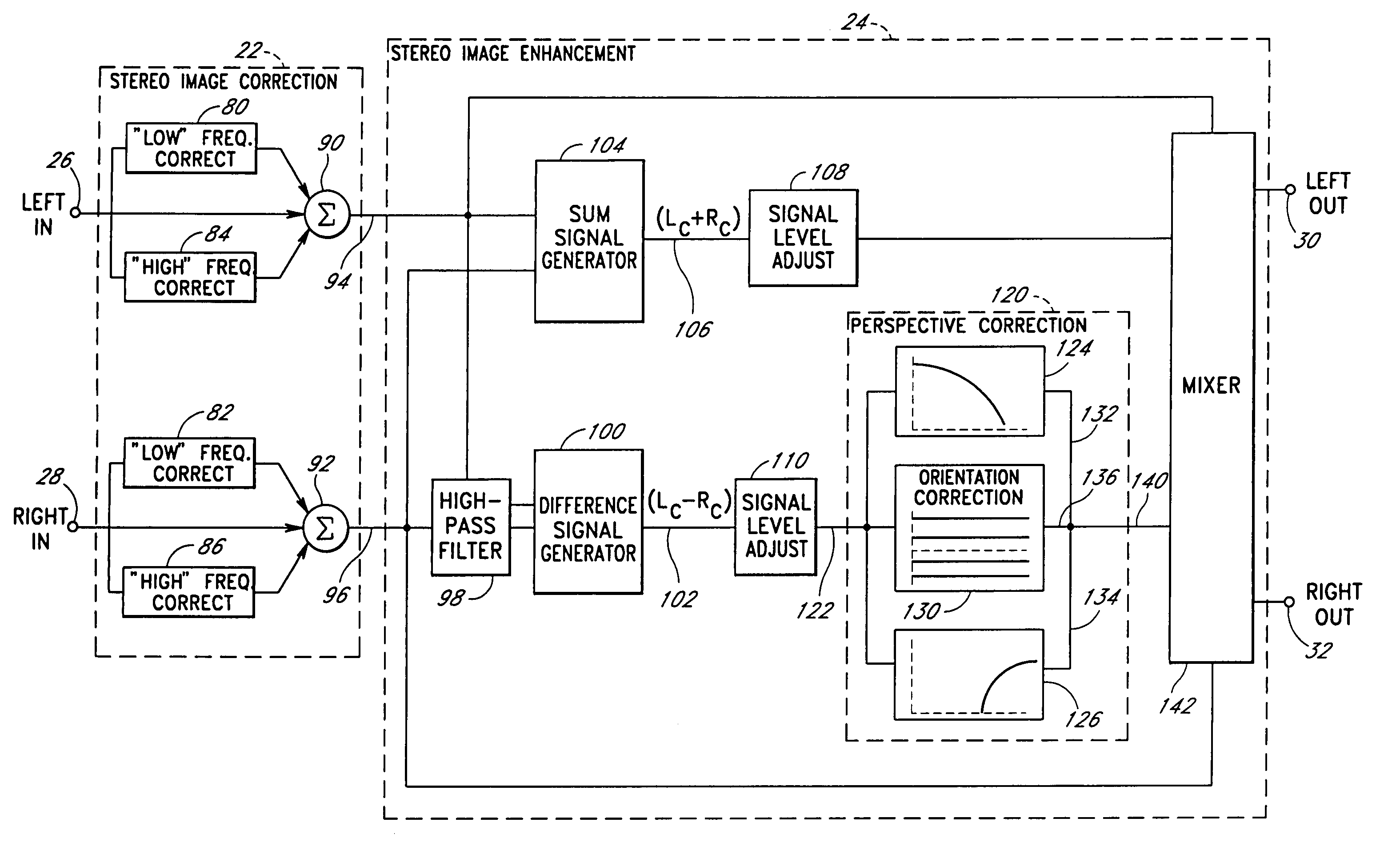
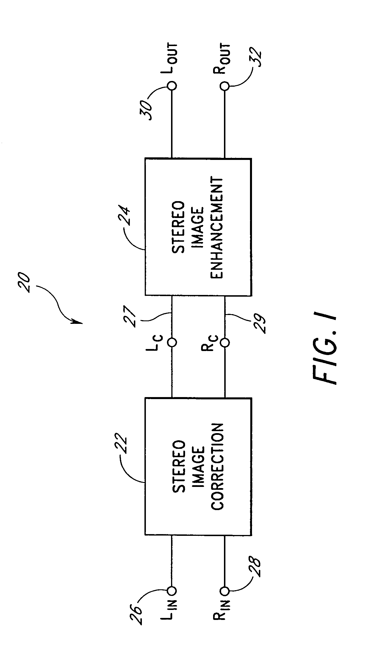
[0092]Referring initially to FIG. 1, a block diagram showing a preferred embodiment of the present invention is shown. Specifically, an acoustic correction apparatus 20 comprises a stereo image correction circuit 22 coupled to a stereo image enhancement circuit 24. The image correction circuit 22 inputs a left stereo signal 26 and a right stereo signal 28. An image-corrected left stereo signal, Lc, and right stereo signal, Rc, are transmitted to the stereo image enhancement device 24 along paths 27 and 29, respectively. The stereo image enhancement circuit 24 processes the signals, Lc and Rc, and provides a left output signal 30 and a right output signal 32. The output signals 30 and 32 may in turn be connected to some other form of signal conditioning circuit, or they may be connected directly to speakers (not shown).

[0093]In a preferred embodiment of the present invention, the stereo image correction circuit 22 and the stereo image enhancement circuit 24 will operate in conjunctio...


PUM


Abstract

An acoustic correction apparatus processes a pair of left and right input signals to compensate for spatial distortion as a function of frequency when the input signals are reproduced through speakers in a sound system. The sound-energy of the left and right input signals is separated and corrected in a first low-frequency range and a second high-frequency range. The resultant signals are recombined to create image-corrected audio signals having a desired sound-pressure response when reproduced by the speakers in the sound system. The desired sound-pressure response creates an apparent sound image location with respect to a listener. The image-corrected signals may then be spatially enhanced to broaden the apparent sound image.

Description

[0001]This application is a continuation of U.S. patent application Ser. No. 09 / 169,352, filed on Oct. 9, 1998, now U.S. Pat. No. 6,718,039, which is a continuation of U.S. patent application Ser. No. 08 / 508,593, filed on Jul. 28, 1995, now U.S. Pat. No. 5,850,453, the entirety of which are hereby incorporated herein by reference.BACKGROUND OF THE INVENTION[0002]1. Field of the Invention[0003]This invention relates generally to audio enhancement systems, and especially those systems and methods designed to improve the realism of stereo sound reproduction. More particularly, this invention relates to apparatus for overcoming the acoustic deficiencies of a sound system as perceived by a listener which can result when speakers within the sound system are not ideally positioned.[0004]2. Description of the Related Art[0005]In a sound reproduction environment various factors may serve to degrade the quality of reproduced sound as perceived by a listener. Such factors distinguish the sound...

Claims


Application Information

Patent Timeline
Patent Type & Authority Patents(United States)
IPC IPC(8): H03G5/00H04S1/00H04R5/02
CPCH03G5/025H04R5/02H04S3/00H04S1/002H04R2499/13H04S1/00
Inventor KLAYMAN, ARNOLD I.KRAEMER, ALAN D.
Owner DTS
Why Eureka
Try Eureka