Non-rigid motion image analysis

a non-rigid motion and image technology, applied in the field of non-rigid motion image analysis, can solve the problems of difficult image noise, and difficult analysis of non-rigid motion, and achieve the effect of improving the model

Inactive Publication Date: 2006-05-09
SIEMENS MEDICAL SOLUTIONS USA INC
View PDF18 Cites 147 Cited by
  • Summary
  • Abstract
  • Description
  • Claims
  • Application Information

AI Technical Summary

Benefits of technology

[0029]The model can be a shape-space of the change in distance between the boundaries, and can be based on a principal component analysis of the way that distance changes. The model can be i

Problems solved by technology

However, the analysis of non-rigid motion, where the object deforms in time, is more difficult.
As well as the problem created by the non-rigid motion of the organ being analysed, these imaging applications in particular have the additional problem that the images are very noisy.
It is often difficult even for trained operators to find desired image features in the image, and thus reliable automatic detection of the features presents considerable difficulty.
However, this scoring scheme is highly subjective.
Also each segment must be classified as normal or abnormal, so it is difficult for a clinician to indicate within the scoring system subtleties such as only part of a segment being abnormal.
While there is therefore a clear need for an automatic method of detecting and quantifying wall motion and wall thickening, the images are extremely difficult to assess automatically.
It will be appreciated that identifying the desired regions of the ventricle is difficult for a human, and that automatic analysis is even more difficult.
However, FIGS. 2(a)–(d) show that this technique is not always useful. FIGS. 2(a) and (c) show the basic echocardiographic

Method used


Image

  • Non-rigid motion image analysis
  • Non-rigid motion image analysis
  • Non-rigid motion image analysis

Examples


Embodiment Construction

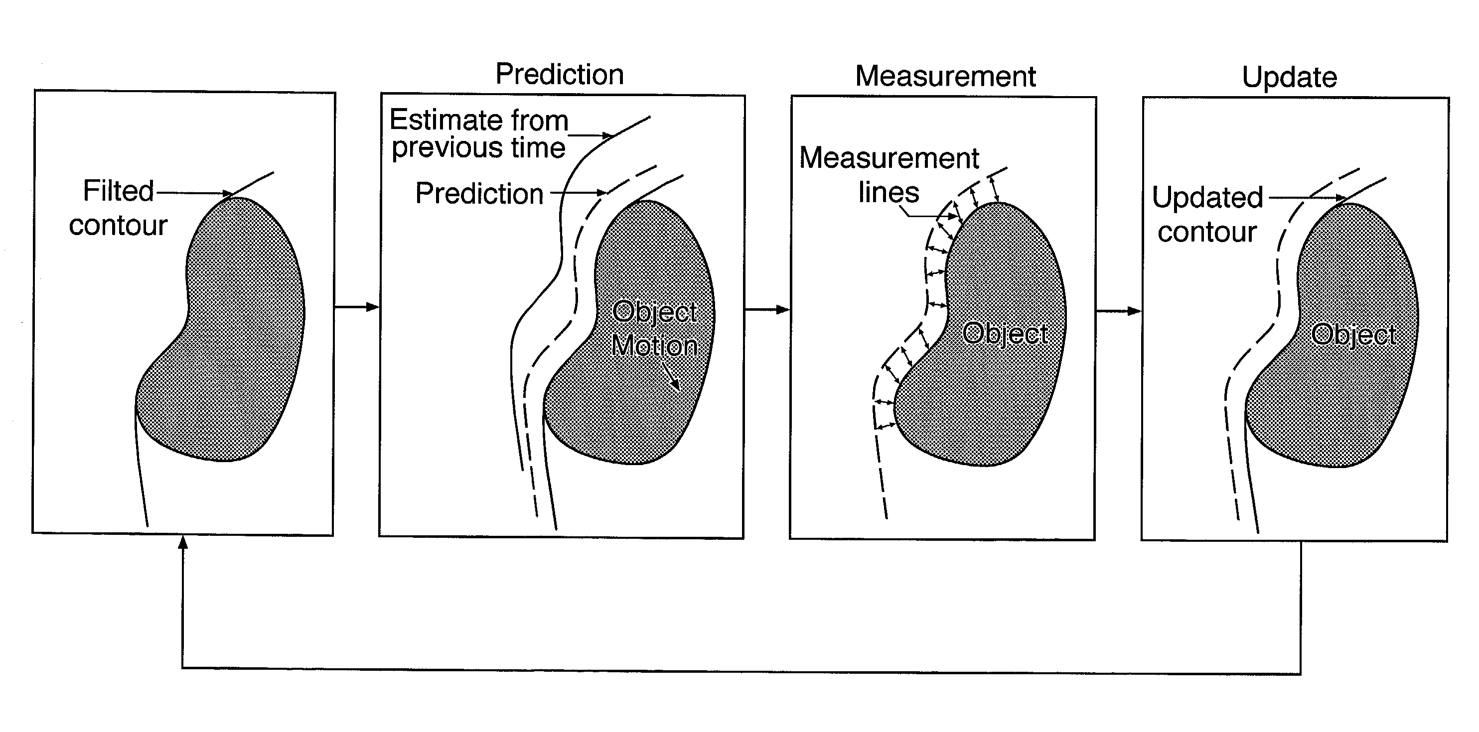
[0067]First of all an embodiment of the invention will be described which is for providing clinically significant quantitative data from an echocardiographic image sequence in which the endocardial wall of the left ventricle has been tracked, for instance using the technique described in Jacob et al mentioned above. It will be recalled that the tracking of the endocardial wall can be defined in terms of the movement of the control points of the spline curve as:—

Q=Q0+WPCAXPCA

[0068]Where the subscript “PCA” indicates that the tracking is based on a principal component analysis. The time varying part is the shape-vector X which can be recovered using a pseudo inverse of the shape-space WPCA:—

XPCA=W*PCA(Q−Q0)[0069]where W*PCA represents the pseudo inverse. However, it will be recalled that FIG. 7 demonstrates that it is not easy to place any clinical significance on the time varying components of X.

[0070]With this embodiment of the present invention, however a new shape space can be us...


PUM


Abstract

A method of analysing a sequence of images of a deformable object in non-rigid motion involves modeling the boundary using a non-rigid contour. A representation of movement of the contour through the sequence of images is calculated using a tracking space shape. The calculated movement representation is decomposed using an interpretational space shape that is different than the tracking space shape.

Description

[0001]This application is the US national phase of international application of PCT / GB00 / 02767 filed 19 Jul. 2000, which designated the US.BACKGROUND AND SUMMARY[0002]The present invention relates to a method of analysing images of a deformable object undergoing non-rigid motion. In particular it relates to a method of analysing the image so that desired image features can be detected and tracked through the sequence, and so that the motion of the features can be automatically quantified and analysed.[0003]Basic techniques for analysing images of objects in motion are relatively straightforward for rigid motion, i.e. where the object does not itself deform. However, the analysis of non-rigid motion, where the object deforms in time, is more difficult. Such non-rigid motion occurs in many situations, but a typical one is in the medical or vetinary imaging field where organs of the human or animal body are imaged in real-time. As well as the problem created by the non-rigid motion of ...

Claims


Application Information

Patent Timeline
IPC IPC(8): G06K9/00A61B6/03A61B5/055A61B6/00A61B8/08G06T1/00G06T7/20
CPCG06T7/2033G06T7/2046A61B6/508G06T2207/30048G06T2207/10132G06T7/0016G06T7/246G06T7/251
Inventor NOBLE, JULIA ALISONJACOB, GARY
Owner SIEMENS MEDICAL SOLUTIONS USA INC
Why Eureka
Try Eureka