
Plastic bag making apparatus

a bag making and plastic bag technology, applied in the field of plastic bag making apparatus, can solve the problems of waste being too small to be pulled and torn by the waste removal means, and the apparatus is therefore problematic with respect to waste, and achieve the effect of convenient waste treatmen

Active Publication Date: 2006-05-16
TOTANI CORP (JP)
View PDF12 Cites 7 Cited by
  • Summary
  • Abstract
  • Description
  • Claims
  • Application Information

AI Technical Summary

Benefits of technology

[0005]Other object of the invention is to provide the apparatus which can successively make the plastic bags with a waste kept continuous to conveniently treat the waste.

Problems solved by technology

The apparatus is therefore problematic with respect to the wastes.
In addition, the wastes may be too small to be pulled and torn by the waste removing means.

Method used


Image

  • Plastic bag making apparatus
  • Plastic bag making apparatus
  • Plastic bag making apparatus

Examples


Embodiment Construction

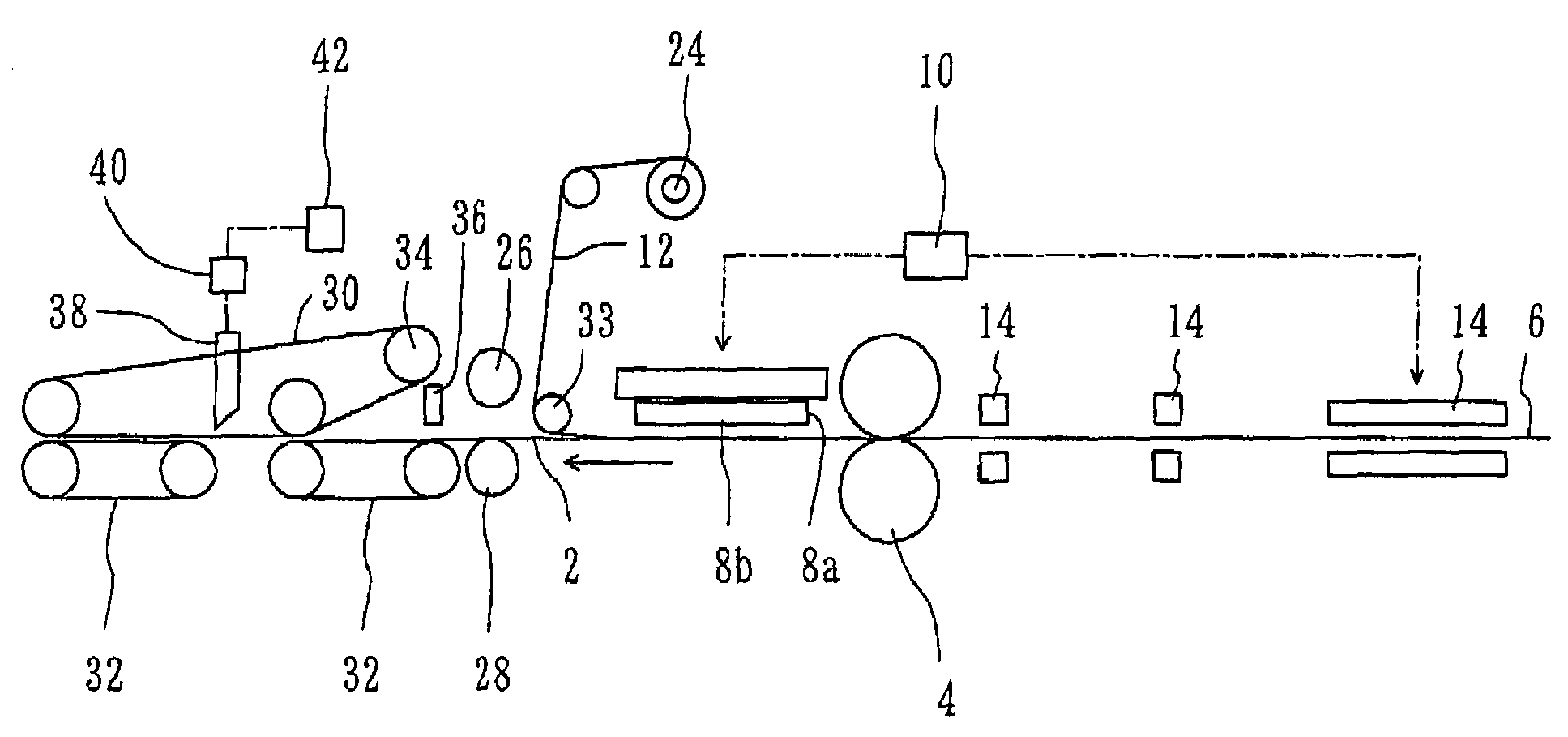
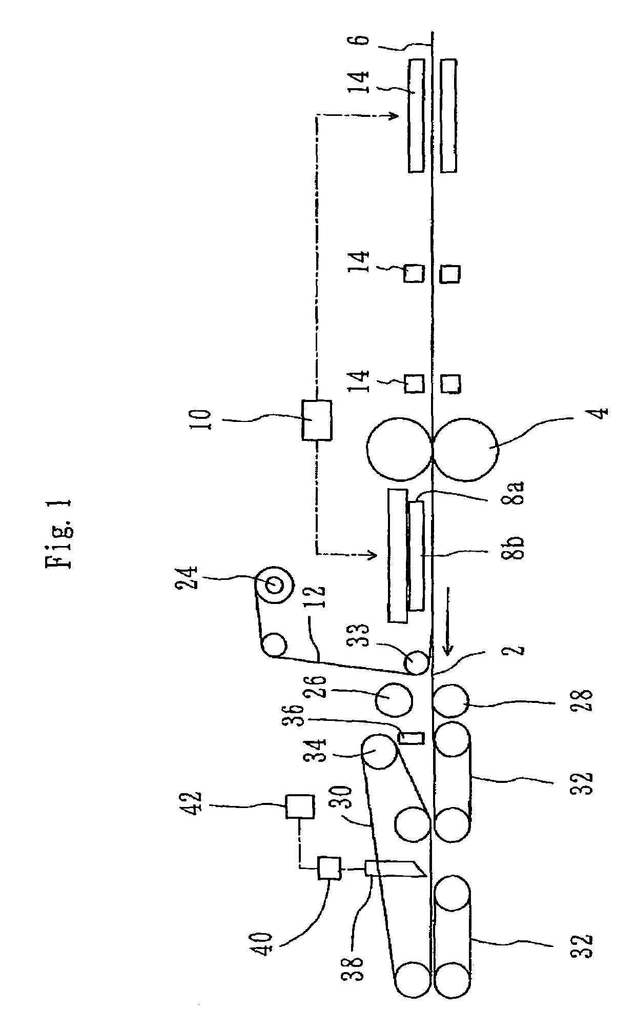
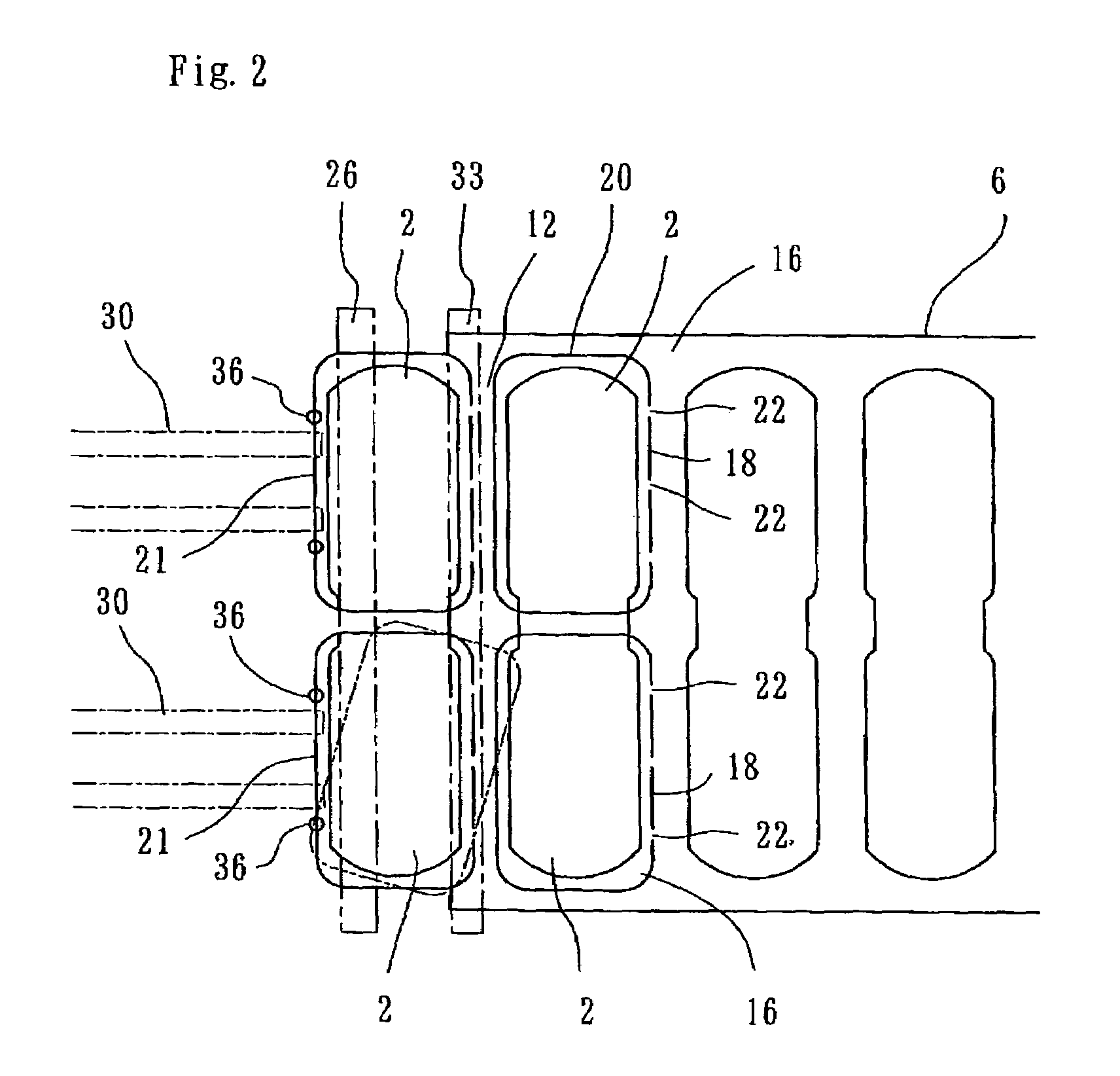
[0022]Referring now to the drawings, FIG. 1 illustrates an apparatus for successively making plastic bags 2 each of which has a shape of circumference, according to the invention. The apparatus includes web feeding means 4 by which a web material 6 is intermittently fed for a length along a longitudinal feeding path. In the embodiment, the web feeding means 4 comprises a pair of feeding rollers between which the web material 6 is sandwiched. The feeding rollers 4 are driven for rotation by drive means such as a motor so that the web material 6 can be intermittently fed for the length along the feeding path which extends horizontally. The web material 6 comprises two or more layers of plastic film.

[0023]The apparatus further includes web cutting means 8a and 8b disposed along the feeding path. The web cutting means 8a and 8b comprises THOMSON blade means opposed to the web material 6. The apparatus further includes drive means 10 by which the THOMSON blade means 8a and 8b is moved to...


PUM

PropertyMeasurementUnit
sizeaaaaaaaaaa
shapeaaaaaaaaaa
circumferenceaaaaaaaaaa

Abstract

An apparatus is arranged to successively make plastic bags each of which has a shape of circumference. The apparatus comprises web feeding means by which a web material is intermittently fed for a length along a longitudinal feeding path. The web material comprises two or more layers of plastic film. Web cutting means is disposed along the feeding path. The web cutting means has a shape corresponding completely or incompletely to the shape of circumference of plastic bag so that the web material can be cut into the shape of circumference of plastic bag by the web cutting means whenever the web material is intermittently fed and temporarily stopped, to successively make the plastic bags with a waste kept continuous. The web cutting means comprises partially cutting means. The plastic bag has an upstream edge along which the web material is partially cut by the partially cutting means so that the plastic bag can be kept connected with the waste at the upstream edge of plastic bag. Drawing means is disposed downstream of the cutting means. The waste is diverged from the plastic bag, directed to and drawn by the drawing means after the web material is cut. Discharge means is disposed downstream of the cutting means. The plastic bag is directed to the discharge means without the waste. The plastic bag is then pulled by the discharge means to be torn from the waste at the upstream edge of plastic bag. The plastic bag is then discharged by the discharge means.

Description

FIELD OF THE INVENTION[0001]The invention relates to an apparatus for successively making plastic bags each of which has a shape of circumference.PRIOR ART[0002]There has been commercially available an apparatus for successively making plastic bags each of which has a shape of circumference, as disclosed in US-2001-0053737. The apparatus includes web feeding means by which a web material is intermittently fed for a length along a longitudinal feeding path. The web material comprises two or more layers of plastic film. The apparatus further includes web cutting means disposed along the feeding path. In the apparatus of the publication, the web material is cut partially or totally by the web cutting means whenever the web material is intermittently fed and temporarily stopped, to successively make plastic bags with wastes taken to pieces.[0003]The apparatus is therefore problematic with respect to the wastes. In the apparatus of the publication, the wastes are pulled by waste removing...

Claims


Application Information

Patent Timeline
Patent Type & Authority Patents(United States)
IPC IPC(8): B32B38/04B31B19/14B31B19/64B31B19/74B32B38/10B26D7/18B26F1/40B29D99/00B31B19/16B31B23/00B31B23/14B31B50/16B65H35/06
CPCB26D7/18B26F1/40B31B19/16B31B23/00B31B41/00B26F2001/407Y10T156/1317B31B2219/145B31B2237/10B31B2241/00Y10T156/1737Y10T156/12B31B2160/10B31B70/16B31B2155/00B31B2155/002B31B2170/00
Inventor TOTANI, MIKIO
Owner TOTANI CORP (JP)
Learn More