High-pressure multi-stage centrifugal compressor

a centrifugal compressor and multi-stage technology, applied in the direction of positive displacement liquid engines, piston pumps, liquid fuel engines, etc., can solve the problems of reducing the pressure ratio of high-pressure stages and the relatively low rotational speed

Inactive Publication Date: 2006-05-16
ATLAS COPCO AIRPOWER NV
View PDF11 Cites 57 Cited by
  • Summary
  • Abstract
  • Description
  • Claims
  • Application Information

AI Technical Summary

Benefits of technology

[0047]The invention aims to remedy the above-mentioned disadvantages and it allows to restrict the characteristic value M of the electric motor for the high-pressure

Problems solved by technology

This strongly reduces the pressure ratio for the high-pressure stag

Method used


Image

  • High-pressure multi-stage centrifugal compressor
  • High-pressure multi-stage centrifugal compressor
  • High-pressure multi-stage centrifugal compressor

Examples


Embodiment Construction

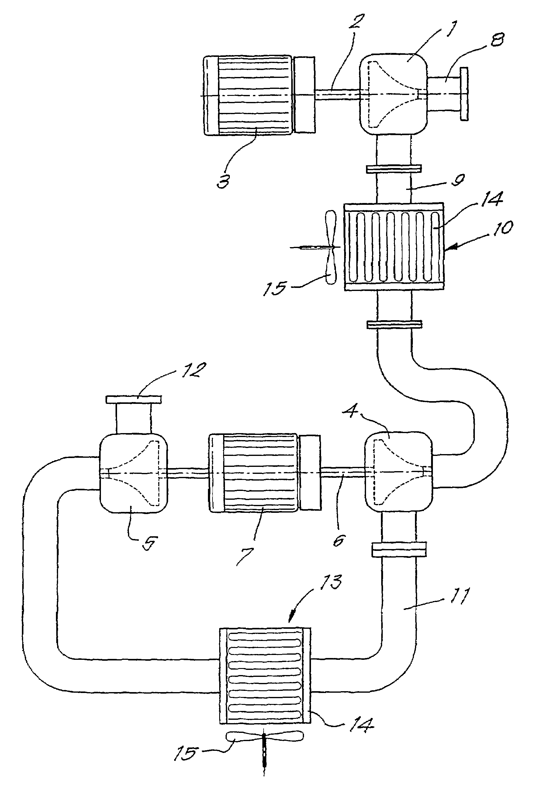
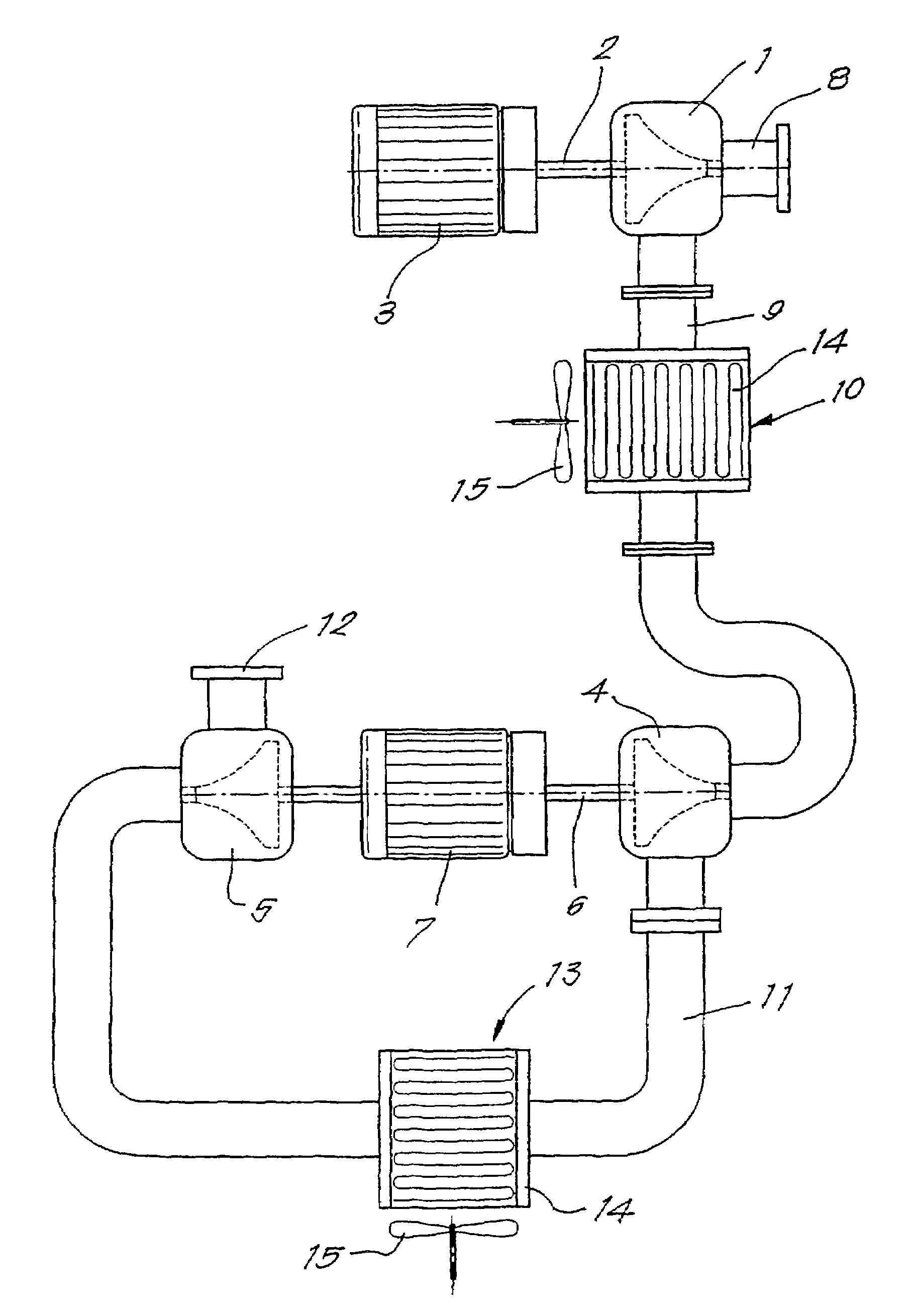
[0056]The high-pressure centrifugal compressor represented in the FIGURE mainly consists of a low-pressure stage formed of a first compressor element 1 whose rotor is driven via a shaft 2 by a first electric high-speed motor 3 and two high-pressure stages formed by two compressor elements 4 and 5 arranged in series which are fixed with their rotors on one and the same shaft 6, however, and which are thus driven via one and the same shaft 6 by a single second high-speed motor 7.

[0057]The compressor element 1 onto which the intake pipe 8 is connected, is connected to the compressor element 4 with its compressed air line 9. In this compressed air line is mounted an intercooler 10 cooled with ambient air or cooling water.

[0058]The compressed air line 11 of the compressor element 4 is connected to the compressor element 5 which is provided with a compressed air line 12 on its outlet. In the first-mentioned compressed air line 11, between the compressor elements 4 and 5, is arranged an ad...


PUM


Abstract

A high-pressure multi-stage centrifugal compressor is provided containing at least three compressor elements which are arranged in series as compressor stages, and at least two electric motors to drive these compressor elements. At least one compressor element forms a low-pressure stage which is driven by an electric motor. At least two compressor elements form high-pressure stages, and are arranged in series and driven by one and the same second electric motor.

Description

FIELD OF THE INVENTION[0001]The present invention concerns a high-pressure multi-stage centrifugal compressor containing at least three compressor elements which are arranged in series as compressor stages, and at least two electric motors to drive these compressor elements.BACKGROUND[0002]A centrifugal compressor element has a high efficiency when its specific speed is situated close to the optimal value. The specific speed Ns is defined as:[0003]Ns=C′·N·QvolDH0.⁢⁢75whereby:[0004]N=the rotational speed of the blade wheel,[0005]Qvol=the volumetric flow on the inlet,[0006]C′=a constant which is amongst others different as a function of the units used,[0007]DH=the adiabatic head of the compressor:[0008]DH=cp·T·(πk-1k-1)whereby:[0009]π=the pressure ratio,[0010]T=the inlet temperature,[0011]cp=the specific heat of the gas at a constant pressure,[0012]k=the ratio of the specific heat of the gas at the constant pressure and the specific heat of the gas at a constant volume.[0013]In order ...

Claims


Application Information

Patent Timeline
IPC IPC(8): F04B23/00F04B25/00F04D29/00F04D25/00F04D27/00F04D29/58F04D29/60
CPCF04D27/02F04D25/00F04C23/00
Inventor FABRY, ERIK PAUL
Owner ATLAS COPCO AIRPOWER NV
Why Eureka
Try Eureka