Encased stone dental model base body and method

a dental model and base body technology, applied in the field can solve problems such as shrinkage, achieve the effects of reducing casting materials, improving the quality of dental model base bodies, and saving time and casting materials

Inactive Publication Date: 2006-05-16
HUFFMAN RONALD E
View PDF122 Cites 27 Cited by
  • Summary
  • Abstract
  • Description
  • Claims
  • Application Information

AI Technical Summary

Benefits of technology

[0008]The present invention is directed to an apparatus and method that provides an improved dental model base having a preformed outer wall and a cast core. The invention provides the advantages of a cast base while improving the quality of the resulting den

Problems solved by technology

Some distortions may result from the shrinkage as

Method used


Image

  • Encased stone dental model base body and method
  • Encased stone dental model base body and method
  • Encased stone dental model base body and method

Examples


Embodiment Construction

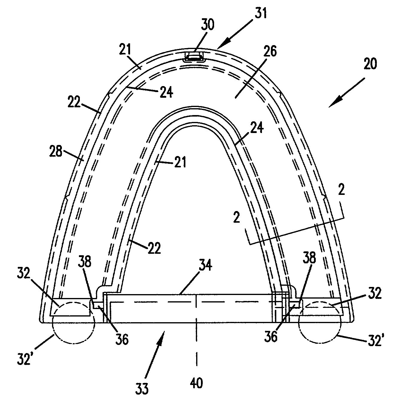
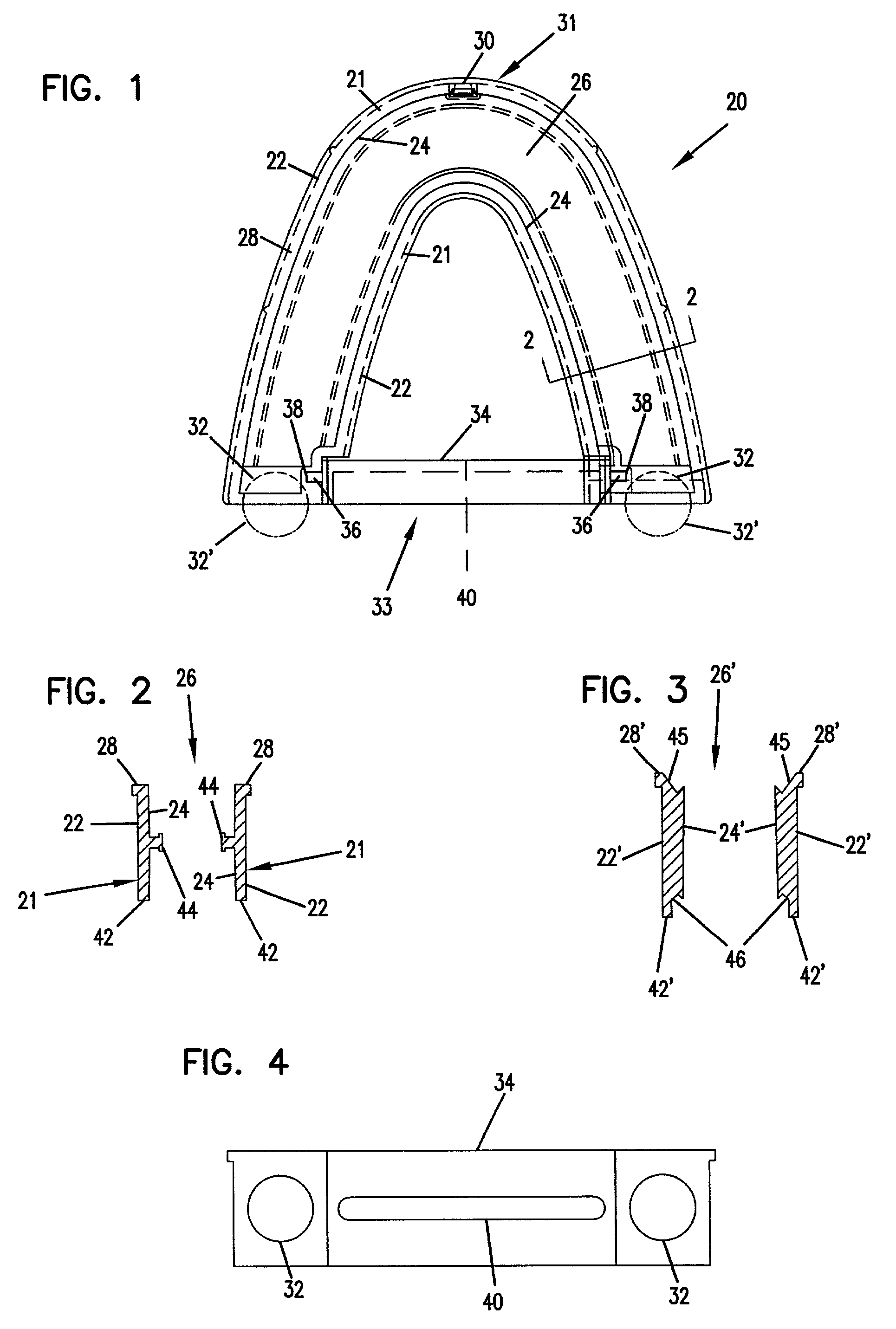
[0036]FIG. 1 depicts a plan view of the dental model encasement member 20. The encasement member has a wall 21 including an exterior surface 22 and an interior surface 24. The interior surface 24 of the wall 21 defines a cavity 26. The cavity follows generally the curvature of a patient's gum line. By analyzing tooth placement on a sampling of gum lines, the inventor has ascertained that three sets of encasement members will correspond generally to the gum lines of most Caucasian patients. A large, medium and small encasement member will correspond to the upper gum line, and a small, medium and large encasement member will correspond generally to the lower gum line. An example of the typical Caucasian tooth placement and gum line is provided in U.S. Pat. No. 5,788,489. Tooth placement and gum curvature for non-Caucasian populations may be found by simply analyzing samplings of that population. Similarly, tooth placement and gum curvatures for Caucasian gum lines other than what the ...


PUM


Abstract

A dental model base having a cast stone core and method for making same. The stone core is cast within an encasement member. The encasement member is adapted for connection to an articulator.

Description

FIELD OF THE INVENTION[0001]The invention relates generally to a dental model base body, and specifically to a base body formed by pouring casting material into a cavity defined by a plurality of walls. Once cured, the casting material, together with the walls of the cavity, form the base body.BACKGROUND OF THE INVENTION[0002]Damaged teeth may be repaired or replaced by crowns, bridge inlays, porcelain veneer or other common dental prosthesis. A successful repair requires accurate alignment and visual uniformity of the repaired tooth with the patient's other teeth. Typically, a model is made of the patient's teeth and the prosthesis is fitted to the model and adjusted to achieve proper alignment and visual uniformity outside the patient's mouth before the prosthesis is applied to the patient.[0003]The model is typically formed by having a patient bite into a pliant casting material which cures to create a mold cavity having a negative impression of the patient's teeth and gums. The ...

Claims


Application Information

Patent Timeline
IPC IPC(8): A61C11/00A61C9/00A61C11/08A61C13/00A61C13/34
CPCA61C9/002A61C11/084A61C11/08A61C13/0027
Inventor HUFFMAN, RONALD E.
Owner HUFFMAN RONALD E
Why Eureka
Try Eureka