Miniature, shielded electrical connector with strain relief

a technology of electrical connectors and strain relief, applied in the direction of electrical apparatus, connection, coupling device connection, etc., can solve the problems of large electrical connector assembly, large number of components, and large size of prior art electrical connector assemblies

Inactive Publication Date: 2006-05-16
HAMILTON SUNDSTRAND CORP
View PDF20 Cites 21 Cited by
  • Summary
  • Abstract
  • Description
  • Claims
  • Application Information

AI Technical Summary

Benefits of technology

[0005]The present invention provides an electrical connector assembly including a wire bundle having at least one wire with a metal shield surrounding at least a portion of the wire. The shield has an end portion and provides electromagnetic interference protection to the wire. A backshell includes a body and a cover secured to the body together defining an internal cavity with the wire at least partially arranged within the cavity. The backshell provides EMI protection for the portion of the wire bundle not covered by the shield. The backshell includes a hole in a wall of either the body or the cover with the end portion of the shield extending through the hole. The clamp is secured about the body and the cover with the end portion of the shield arranged between the clamp and the backshell grounding the shield to the backshell. The clamp forces the backshell into engagement with the wire bundle to provide strain relief for the wire bundle.
[0006]Accordingly, the above invention provides a smaller electrical connector assembly providing EMI protection and strain relief.

Problems solved by technology

Prior art electrical connector assemblies are rather large and includes numerous components.
Using the sleeve and strain relief nut results in a rather large electrical connector assembly.

Method used


Image

  • Miniature, shielded electrical connector with strain relief
  • Miniature, shielded electrical connector with strain relief
  • Miniature, shielded electrical connector with strain relief

Examples


Embodiment Construction

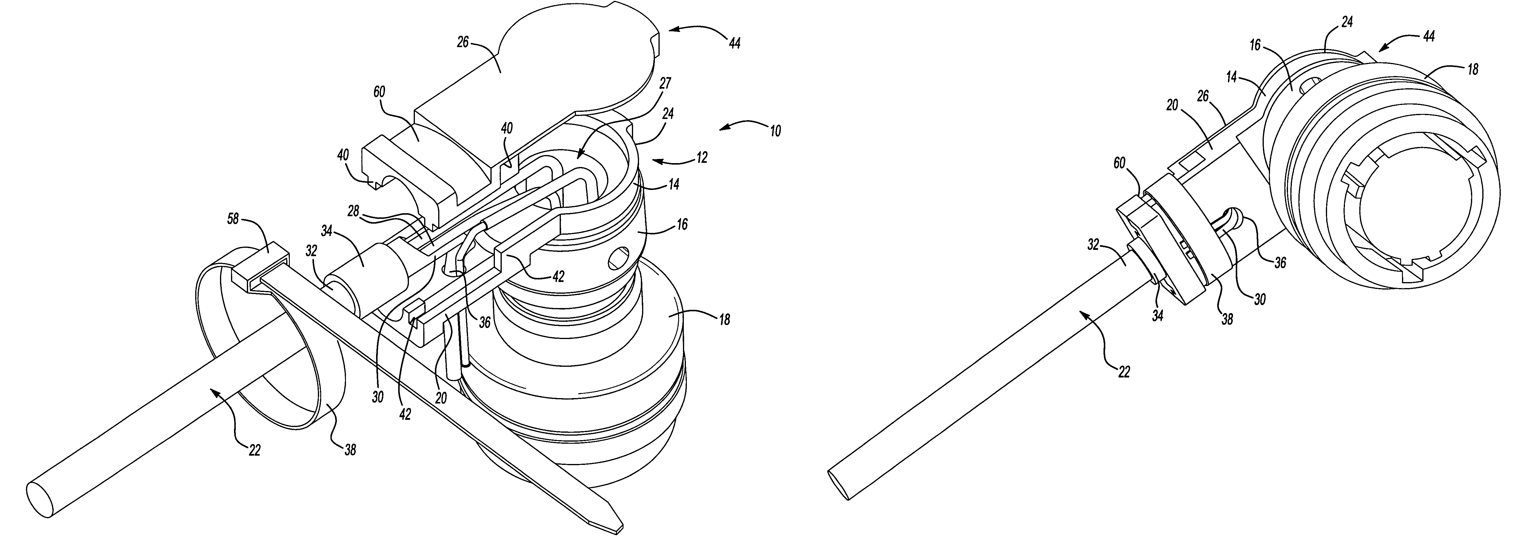
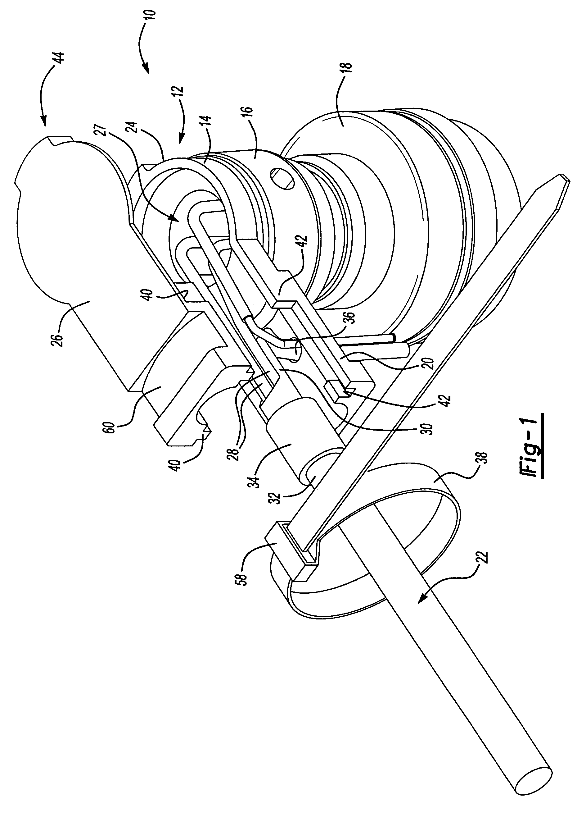
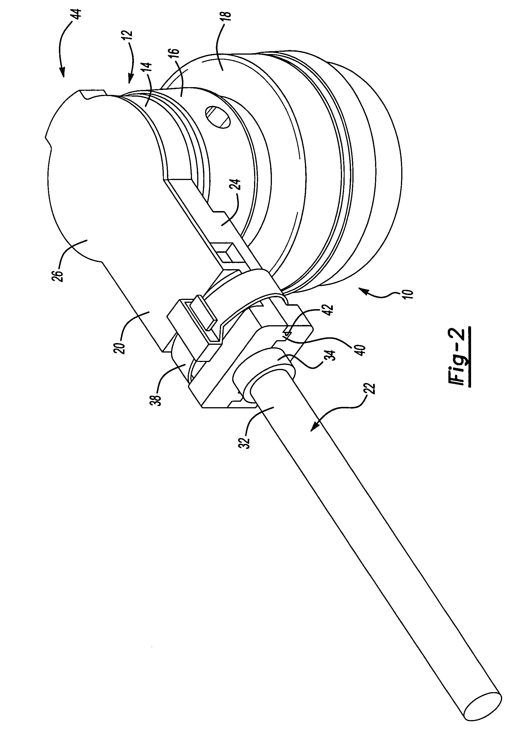
[0012]An electrical connector assembly 10 is shown in FIGS. 1–3. The assembly 10 includes a backshell 12, which is preferably constructed from a nickel plated aluminum. The backshell 12 includes a base portion 14 having a coupling nut 16 that is threadingly secured to a connector 18. The connector 18 is attached to a corresponding connector on the space suit, which is electrically connected to a sensor monitoring a characteristic of the occupant within the space suit. However, it is to be understood that the present invention electrical connector assembly 10 may be used in any suitable application.

[0013]The backshell 12 includes an elongated portion 20 extending transversely from the base portion 14 so that the assembly 10 with its wire bundle 22 may fit closely against the space suit. The wire bundle 22 enters an opening in the elongated portion 20. The backshell 12 includes a body 24 and cover 26, which together define an internal cavity 27 receiving the wires 28 of the wire bundl...


PUM


Abstract

An electrical connector assembly includes a wire bundle having at least one wire with a metal shield surrounding at least a portion of the wire. The shield has an end portion and provides electromagnetic interference protection to the wire. A backshell includes a body and a cover secured to the body together defining an internal cavity with the wire at least partially arranged within the cavity. The backshell provides EMI protection for the portion of the wire bundle not covered by the shield. The backshell includes a hole in a wall of either the body or the cover with the end portion of the shield extending through the hole. The clamp is secured about the body and the cover with the end portion of the shield arranged between the clamp and the backshell grounding the shield to the backshell. The clamp forces the backshell into engagement with the wire bundle to provide strain relief for the wire bundle.

Description

[0001]The invention described herein was made in the performance of work under NASA Contract No. NAS9-97150 and is subject to the provisions of Section 305 of the National Aeronautics and Space Act of 1958 (42 U.S.C. 2457).BACKGROUND OF THE INVENTION[0002]This invention relates to an electrical connector assembly with shielding, and more particularly, the invention relates to strain relief and electromagnetic interference shielding of a wire bundle and electrical connector for use with a space suit.[0003]Space suits used in outerspace typically include a primary life support system having numerous sensors monitoring various characteristics of the occupant of the space suit. Information is transmitted from the sensors to a computer by wires. The wires are connected to the sensors by an electrical connector, which must be as small and light as possible to be accommodated on the space suit. To ensure reliable data transmission over the wires, the wire bundle typically includes a shield...

Claims


Application Information

Patent Timeline
Patent Type & Authority Patents(United States)
IPC IPC(8): H01R9/03H01R9/05H01R13/58
CPCH01R13/582H01R9/0527
Inventor DIEP, CHUONG H.
Owner HAMILTON SUNDSTRAND CORP
Why Eureka
Try Eureka