
Collarless shoulder arthroplasty prosthesis

a technology for shoulder joint and prosthesis, applied in the field of joint prosthesis improvement, can solve the problems of reduced range of motion, loss of useful articular surface, and increased cost of shoulder joint replacement, and achieve the effect of full range of motion, reduced or eliminated joint overstuffing, and modularity

Inactive Publication Date: 2006-05-16
DEPUY ORTHOPAEDICS INC
View PDF23 Cites 45 Cited by
  • Summary
  • Abstract
  • Description
  • Claims
  • Application Information

AI Technical Summary

Benefits of technology

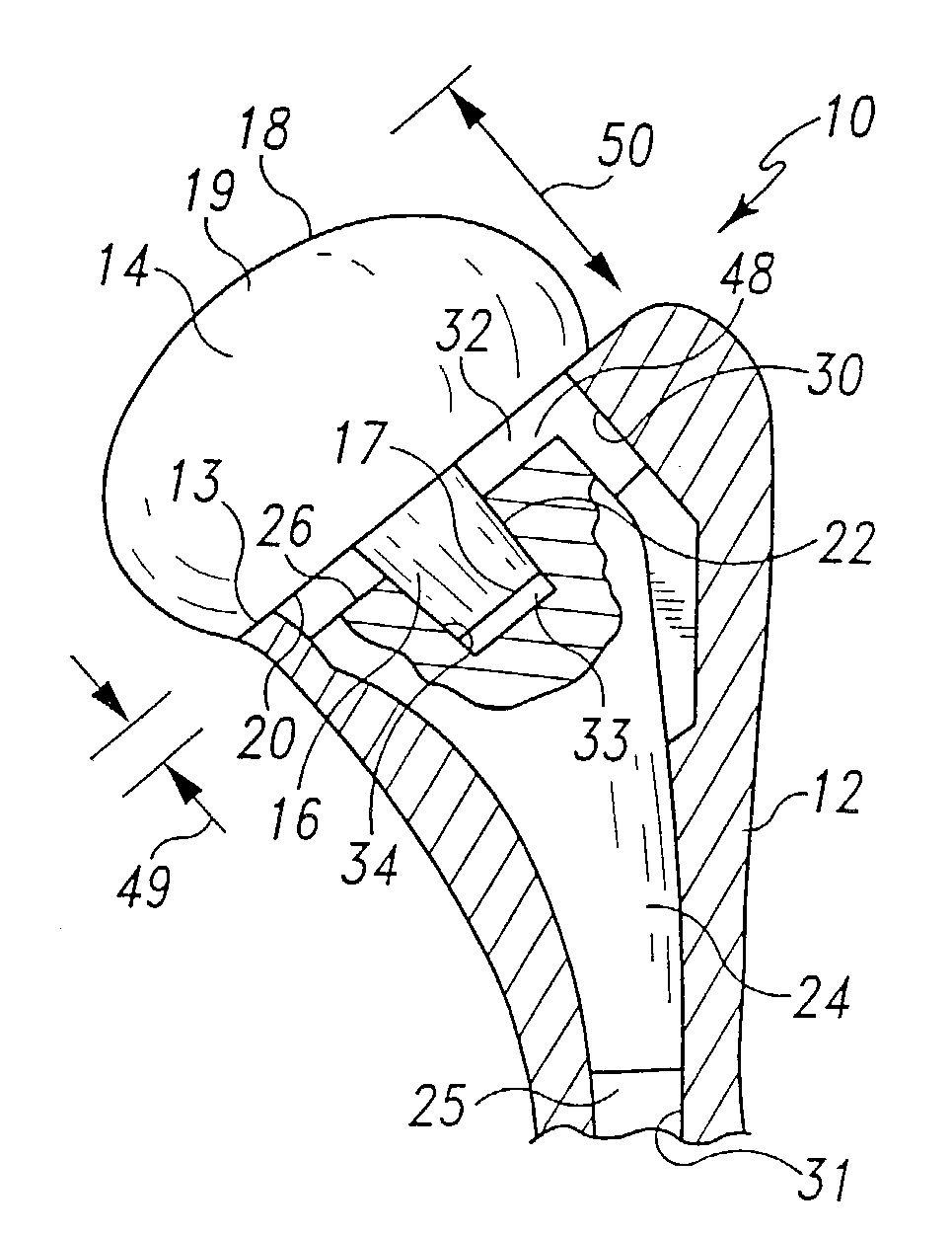
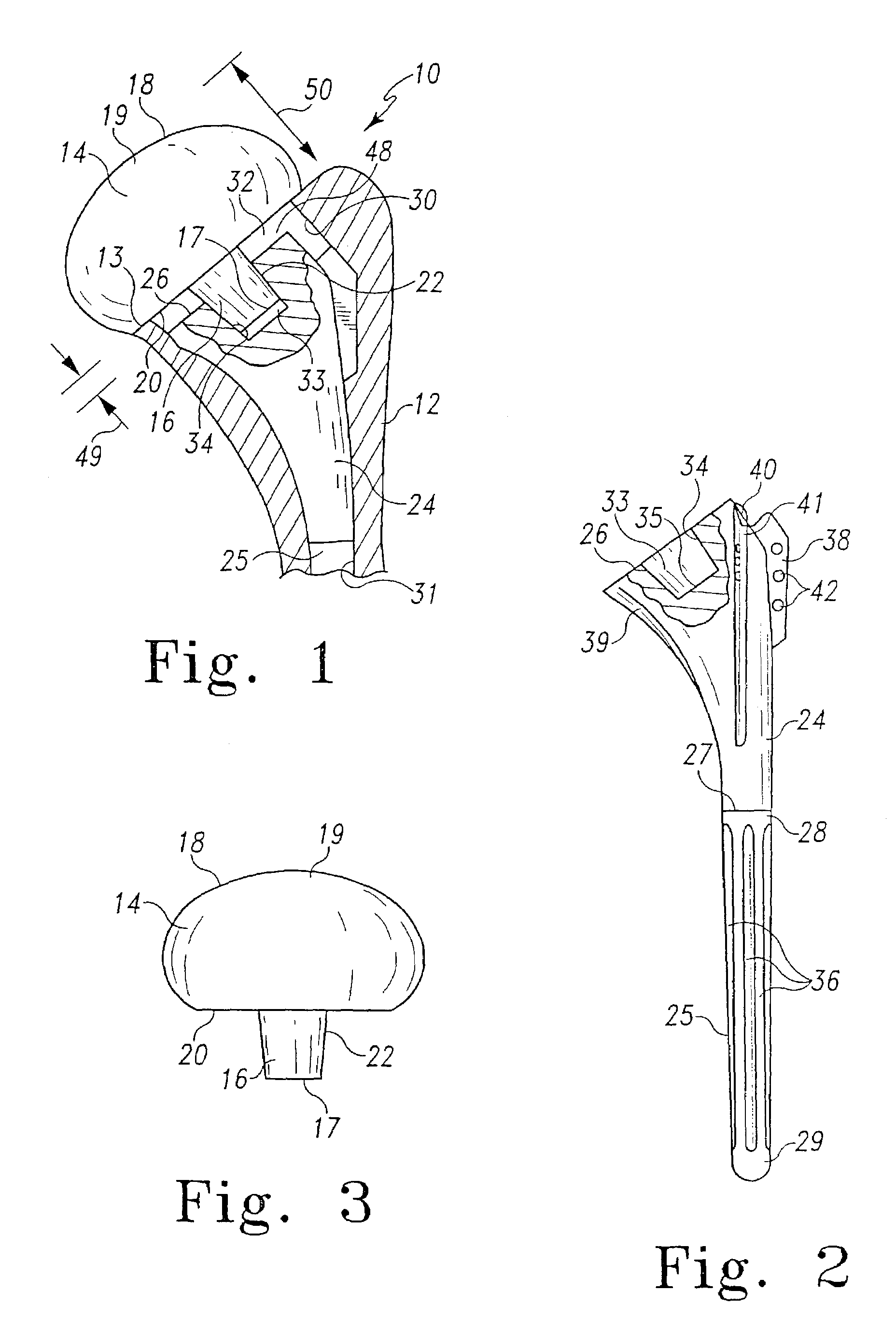
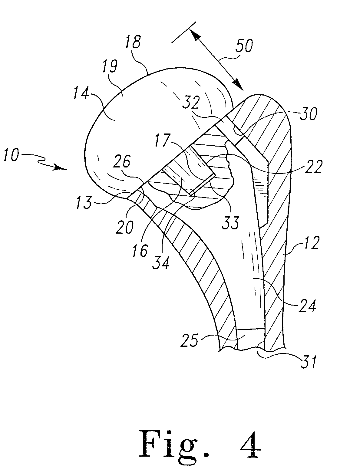
[0004]The shoulder prosthesis of the present invention comprises a modular humeral prosthesis component employing a collarless design. A body portion of the prosthesis is provided without a collar, and it may be implanted into a prepared proximal end of a humerus such that the body sits recessed below the level of the cut proximal surface of the humerus. A head portion is provided in which a support surface of the head functions as collar by direct apposition of it to the cut proximal humerus. The modular connection is thus recessed below the proximal bone surface. By providing a modular connection which is recessed below the bone surface, the benefits of modularity may be retained, while joint overstuffing may be reduced or eliminated, and a substantially full range of motion may be achieved.

Problems solved by technology

The collar, however, occupies joint space, and as compared to an analogous prosthesis of a non-modular design, a modular prosthesis with a collar may require additional joint space.
This additional joint space may cause “overstuffing” of the glenohumeral joint, resulting in a decrease in range of motion.
However, use of these prostheses still may result in overstuffing and a loss of useful articular surface.

Method used


Image

  • Collarless shoulder arthroplasty prosthesis
  • Collarless shoulder arthroplasty prosthesis
  • Collarless shoulder arthroplasty prosthesis

Examples


Embodiment Construction

[0016]The present invention relates to a modular shoulder joint prosthetic device 10 which employs a collarless design. FIG. 1 shows a proximal end of a humerus 12 which has been prepared for joint replacement by removal of the natural humeral head (not shown). Prepared humerus 12, as shown in FIG. 1, has received prosthetic device 10 of this invention. Prosthetic device 10 is the humeral component of a prosthetic shoulder joint, and prosthetic device 10 comprises a body 24 and a head 14.

[0017]Still referring to FIG. 1, humerus 12, as prepared to receive prosthetic device 10, has a proximal bone surface 13 and an opening 32 extending through proximal bone surface 13 to a medullary passageway 31. Body 24 is seated within humerus 12 and has an elongated shaft 25 which extends into medullary passageway 31. As shown, body 24 is provided with a proximal surface 26 which is recessed below proximal bone surface 13. Humeral head 14 is secured to body 24. Humeral head 14 is provided with a s...


PUM


Abstract

A shoulder prosthesis of the present invention includes a modular humeral prosthesis component employing a collarless design. A body portion of the prosthesis is provided without a collar, and it may be implanted into a prepared proximal end of a humerus such that the body sits recessed below the level of the cut proximal surface of the humerus. A head portion is provided in which a support surface of the head functions as collar by direct apposition of it to the cut proximal humerus. The modular connection is thus recessed below the proximal bone surface. By providing a modular connection which is recessed below the bone surface, the benefits of modularity may be retained, while joint overstuffing may be reduced or eliminated, and a substantially full range of motion may be achieved.

Description

[0001]This application is a continuation of U.S. patent application Ser. No. 09 / 543,118, filed on Apr. 5, 2002, now U.S. Pat. No. 6,508,840, that, in turn, claims the benefit of U.S. Provisional Application Ser. No. 60 / 128,134 that was filed on Apr. 7,1999.TECHNICAL FIELD OF THE INVENTION[0002]The present invention relates to improvements in joint prostheses; more particularly to improvements in shoulder joint prostheses which employs a collarless design.BACKGROUND OF THE INVENTION[0003]Shoulder joint prostheses are known in the art. See, for example, U.S. Pat. Nos. 4,919,669 and 5,738,161, hereby incorporated by reference. A typical shoulder prosthesis comprises a body, which is for implantation into a prepared humerus, and a head, which is fixed to the body and provides a bearing surface. Modular shoulder prostheses are also known. See, for example, U.S. Pat. No. 5,314,479, hereby incorporated by reference. U.S. Pat. No. 5,314,479 discloses a modular prosthesis comprising a body, ...

Claims


Application Information

Patent Timeline
IPC IPC(8): A61F2/40A61F2/38A61B17/06A61F2/00A61F2/30A61F2/46
CPCA61F2/40A61B17/06166A61F2250/0026A61F2/4059A61F2002/30322A61F2002/30332A61F2002/30405A61F2002/30604A61F2002/30616A61F2002/30827A61F2002/30884A61F2002/30896A61F2002/30902A61F2002/4018A61F2002/4055A61F2002/4062A61F2002/4074A61F2002/4077A61F2002/4631A61F2220/0025A61F2220/0033A61F2002/4051
Inventor ROCKWOOD, JR., CHARLES A.ONDRLA, JEFFREY M.
Owner DEPUY ORTHOPAEDICS INC
Learn More