Magneto-resistance effect element bar exposure method

a technology of magneto-resistance effect and element bar, which is applied in the direction of instruments, photomechanical equipment, originals for photomechanical treatment, etc., can solve the problems of poor distribution of mr height within the mr element bar

Inactive Publication Date: 2007-03-20
TDK CORPARATION
View PDF3 Cites 1 Cited by
  • Summary
  • Abstract
  • Description
  • Claims
  • Application Information

AI Technical Summary

Benefits of technology

[0007]The present invention was conceived in view of the above problems and has, as an object, the provision of an MR element bar that permits the fabrication of MR elemen

Problems solved by technology

As a result, because there is a variation in the average value and distribution of the position coordinates of the MR elements in the

Method used


Image

  • Magneto-resistance effect element bar exposure method
  • Magneto-resistance effect element bar exposure method
  • Magneto-resistance effect element bar exposure method

Examples


Embodiment Construction

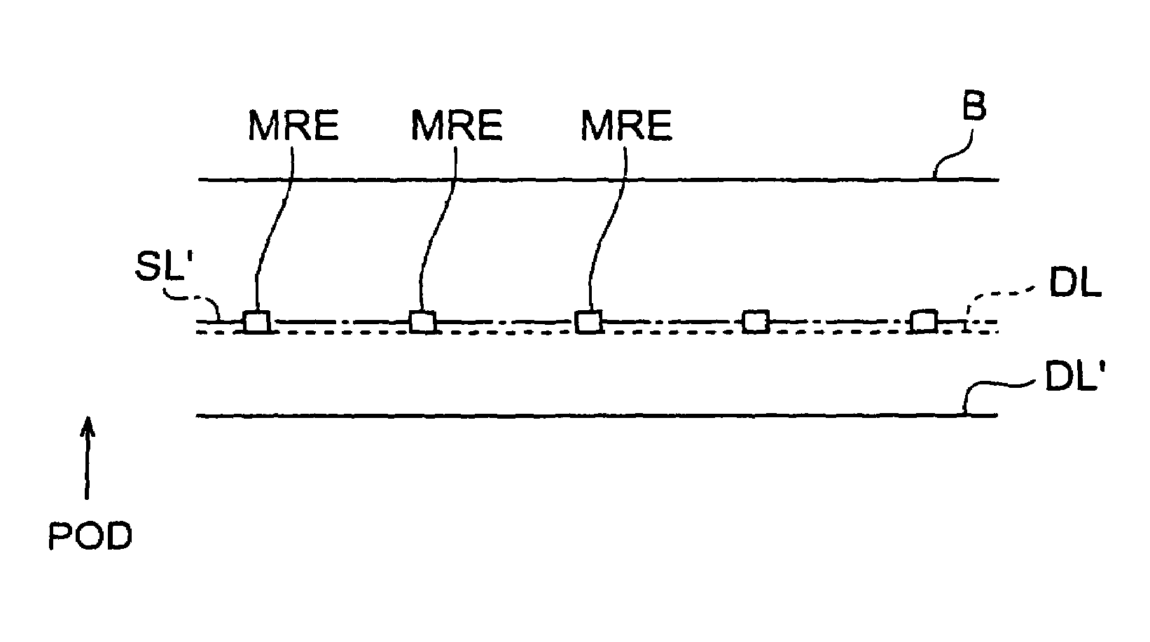
[0028]An MR element bar according to an embodiment as well as an exposure method and formation method for this MR element bar will be described below. The same reference numerals have been assigned to the same elements and hence repetition in the description is avoided.

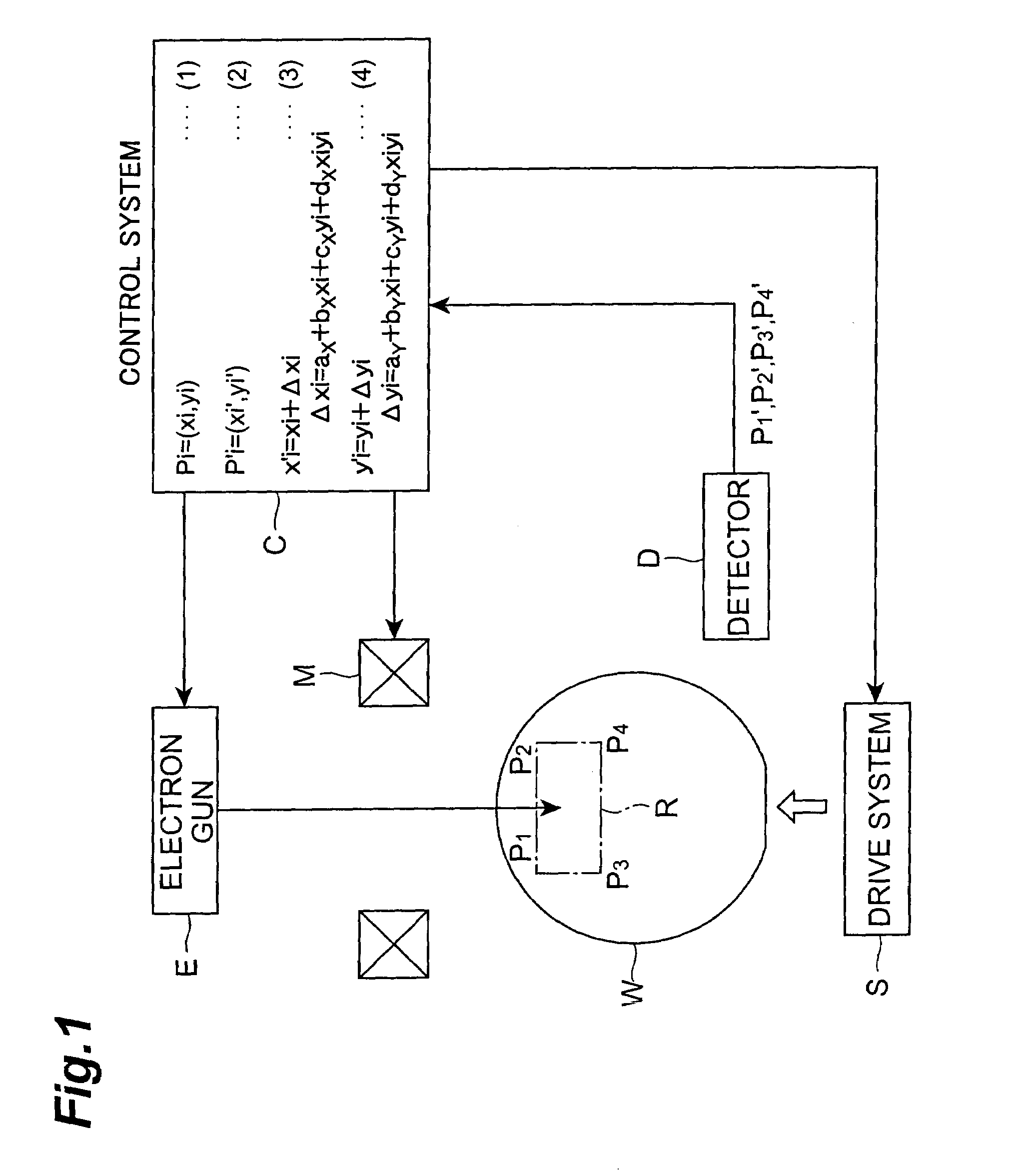
[0029]FIG. 1 is a block diagram of the MR element bar exposure device.

[0030]The exposure device comprises an electron gun (beam exposure source) E for applying an electron beam to an AlTiC wafer (substrate) W; a deflector coil (beam shifting means) M for deflecting the electron beam emitted by the electron gun E; a drive system S on which the wafer W is mounted and which shifts the wafer W in a horizontal direction (within the substrate plane); and a detector D for detecting the position (coordinates) in the horizontal plane of alignment marks P1 to P4 formed on the wafer W. Because the exposure performed using the exposure device is electron beam exposure, exposure can be performed at a high resolution.
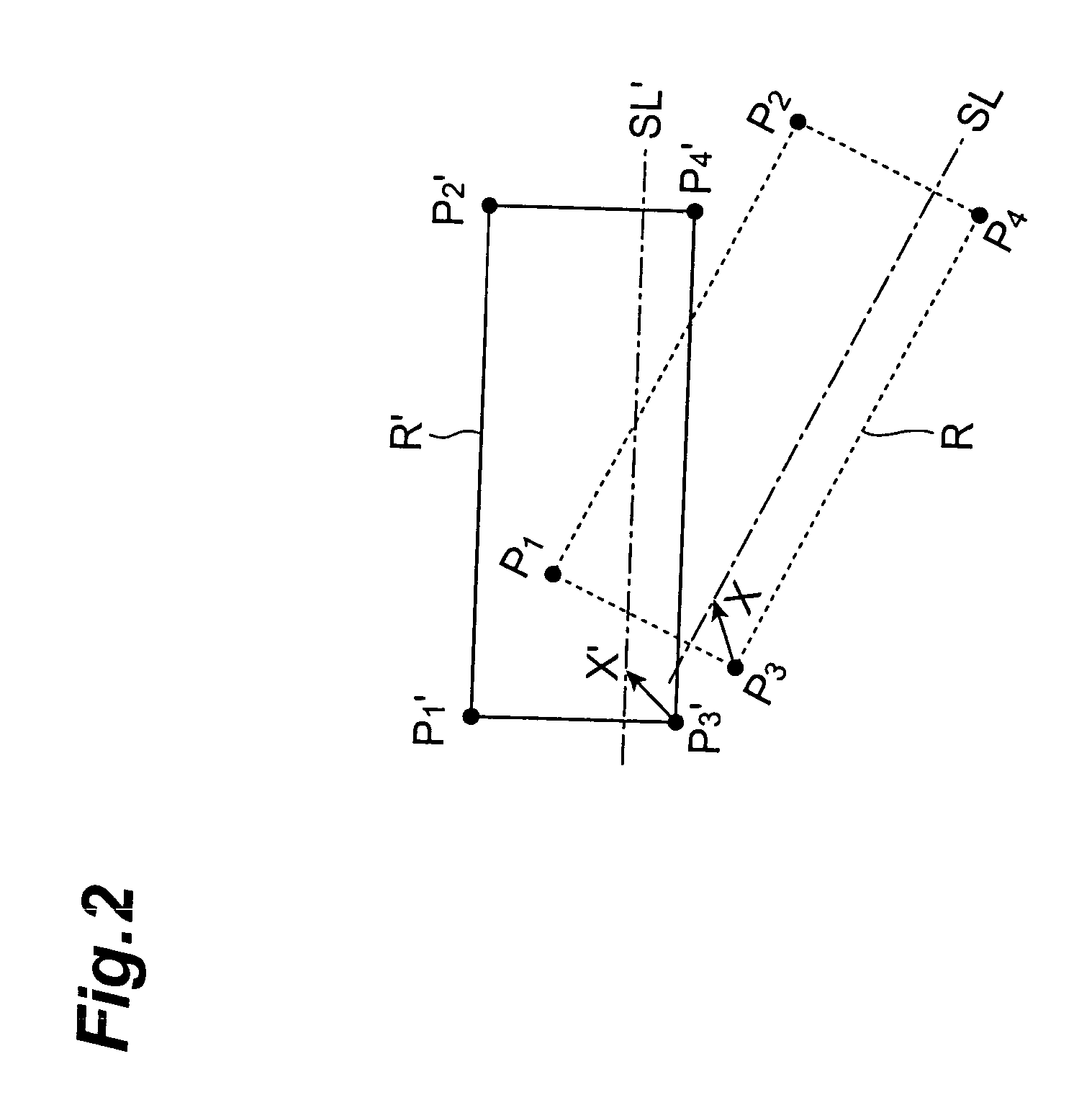
[0031]The coor...


PUM

PropertyMeasurementUnit
Thicknessaaaaaaaaaa
Electrical resistanceaaaaaaaaaa

Abstract

The present invention provides an MR element bar that permits the fabrication of MR elements in which a variation in characteristics is suppressed, as well as an MR element bar exposure method and formation method enabling the fabrication of the MR element bar. The MR element bar exposure method according to the present invention comprises the steps of: detecting the positions of a plurality of alignment marks P1 to P4 formed on a wafer W; correcting an exposure position correction region R on the basis of the positions of detected alignment marks P1′ to P4′; and exposing a resist which is formed on the wafer W, wherein an MR element bar region B comprises a plurality of MR elements (patterns MRE) aligned in the longitudinal direction of the region B, and one exposure position correction region R is established for one MR element bar region B.

Description

BACKGROUND OF THE INVENTION[0001]1. Field of the Invention[0002]The present invention relates to a magneto-resistance effect element bar exposure method, a magneto-resistance effect element bar formation method, and a magneto-resistance effect element bar.[0003]2. Related Background Art[0004]The increased capacity and miniaturization of magnetic disk devices as well as the higher recording densities thereof have established a need for improvements in the performance of thin-film magnetic heads.[0005]The creation of a thin-film magnetic head involves first cutting a magneto-resistance effect element bar that comprises several tens to several hundreds of magneto-resistance effect elements (referred to hereinafter as MR elements) which are lined up in a row in the longitudinal direction of the bar, from a substrate. The cut faces parallel to the longitudinal direction are then polished to obtain an MR element bar that comprises MR elements that possess the desired MR element height, th...

Claims


Application Information

Patent Timeline
IPC IPC(8): G11B5/39
CPCB82Y10/00B82Y25/00G11B5/3909G11B5/3903Y10T29/49036G11B2005/3996
Inventor KAGOTANI, LEGAL REPRESENTATIVE, TERUYOHATATE, HITOSHIKASAHARA, NORIAKIKUWASHIMA, TETSUYAKAGOTANI, DECEASED, TSUNEO
Owner TDK CORPARATION
Why Eureka
Try Eureka