Power supply unit having uniform battery characteristic

a power supply unit and characteristic technology, applied in the field of power supply units, can solve the problems of deterioration of battery performance and life, inadequacies, and increase in the temperature of the battery, so as to reduce the variation in characteristics and lives of battery cells, suppress the increase in the volume of the entire power supply unit, and reduce the effect of battery cell variation

Inactive Publication Date: 2009-03-31
TOYOTA JIDOSHA KK
View PDF17 Cites 15 Cited by
  • Summary
  • Abstract
  • Description
  • Claims
  • Application Information

AI Technical Summary

Benefits of technology

[0034]According to the present invention, a power supply unit compactly accommodating components corresponding to a mounting limitation of a vehicle can be structured, and a need for a higher-voltage battery can also be satisfied.
[0035]Further, since the component box is formed in the shape of a substantially flat plate and placed at the center of a side surface of the battery pack to extend along the direction in which the battery groups are layered, an increase in the volume of the entire power supply unit due to an increase in the volume of the batteries can be suppressed, and variations in characteristics and lives among battery cells can be reduced.
[0036]Furthermore, since the component box is placed in contact with the cooling wind passage in the battery pack to allow the battery pack and the component box to be cooled down simultaneously with a single cooling fan, the component box can be miniaturized and cooling efficiency of the cooling device can be improved.
[0037]Further, since the component box is formed in the shape of a substantially thin flat plate, a reduction in the volume of the luggage space due to the increase in the volume of the batteries can be suppressed.

Problems solved by technology

Since a nickel metal hydride battery, a lithium ion battery or the like is mainly used as such a battery, reaction heat is generated by chemical reaction when the battery is charged, causing an increase in the temperature of the battery.
The increase in the battery temperature results in deterioration of the performance and life of the battery.
Although dividing the battery group within battery pack 100 and separately placing the divided battery subgroups can be considered as one solution to attain a higher-voltage battery, the solution is not appropriate because it requires a space and cost for placing each of the divided battery subgroups.

Method used


Image

  • Power supply unit having uniform battery characteristic
  • Power supply unit having uniform battery characteristic
  • Power supply unit having uniform battery characteristic

Examples


first embodiment

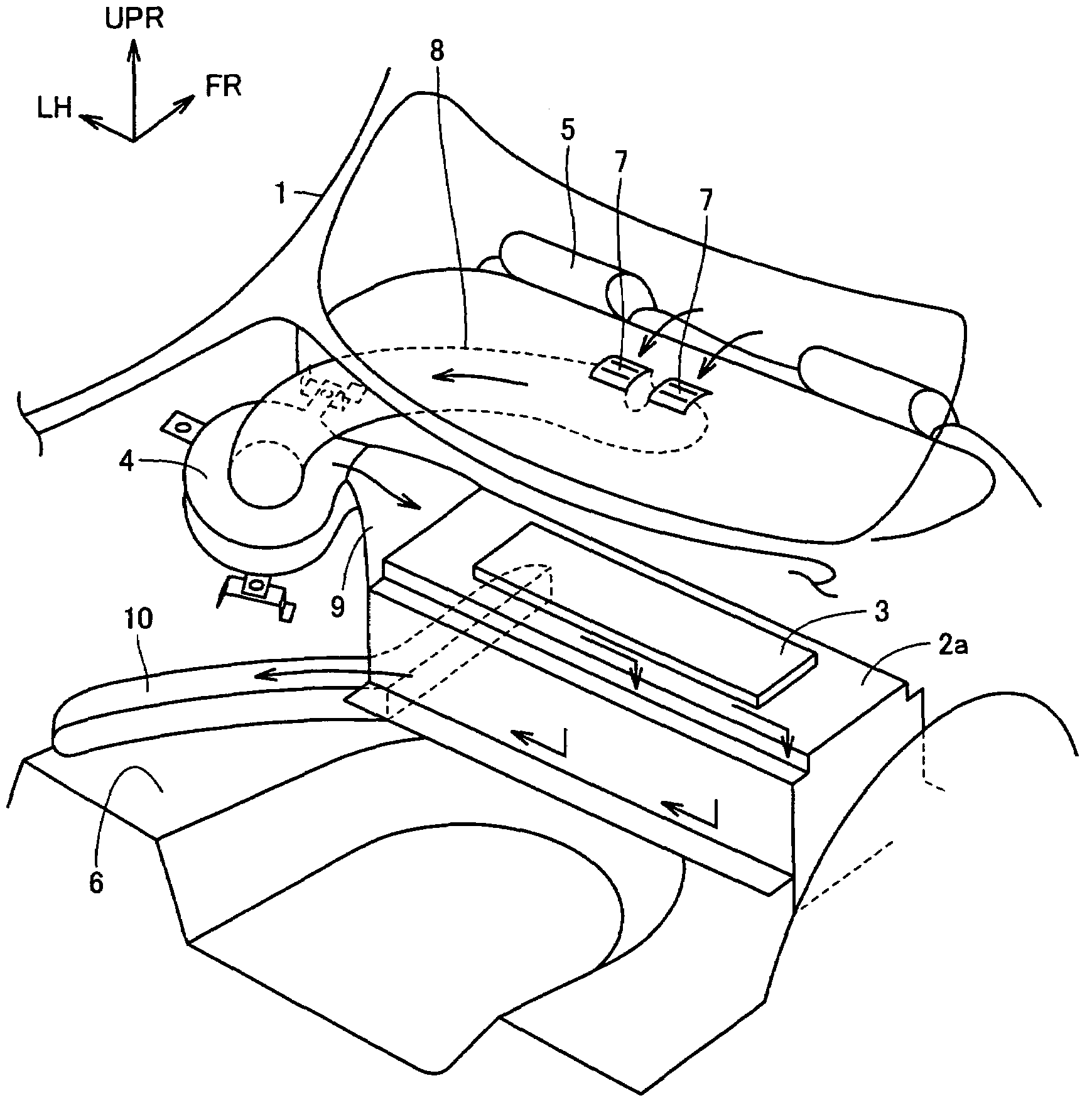
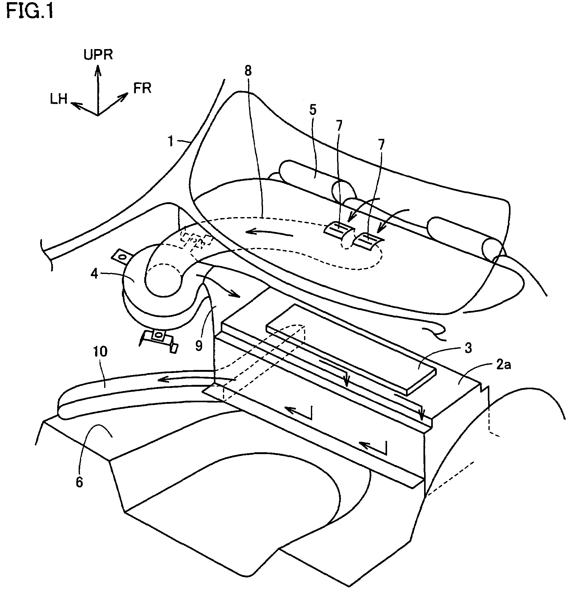
[0048]FIG. 1 is a perspective diagram of a vehicle equipped with a power supply unit in accordance with a first embodiment of the present invention.

[0049]Referring to FIG. 1, the power supply unit is placed on the floor of luggage space 6 located behind rear seat 5 of a vehicle 1. The power supply unit includes a battery pack 2a, a component box 3, and a cooling fan 4. It is to be noted that the direction indicated by arrow UPR in FIG. 1 shows the direction toward the ceiling of vehicle 1 (upward direction), the direction indicated by arrow FR shows the forward direction (moving direction) of vehicle 1, and the direction indicated by arrow LH shows the direction toward the left side of vehicle 1 (left-side direction).

[0050]Battery pack 2a has a structure accommodating a module as a battery set within a casing as an exterior material for battery pack 2a. The module is formed of a plurality of layered battery groups. Between the layered battery groups, a gap as a cooling wind passage ...

second embodiment

[0088]FIG. 5 is a perspective diagram of a vehicle equipped with a power supply unit in accordance with a second embodiment of the present invention.

[0089]Referring to FIG. 5, the power supply unit is placed on the floor of luggage space 6 located behind rear seat 5, as in the first embodiment. The power supply unit includes a battery pack 2b, component box 3, and cooling fan 4.

[0090]Battery pack 2b has a structure basically similar to that of battery pack 2a shown in FIG. 3. FIG. 6 is a view illustrating a structure of battery pack 2b shown in FIG. 5.

[0091]Referring to FIG. 6, battery pack 2b has a structure accommodating module 22 within casing 21 as an exterior material. In module 22, a gap as a cooling wind passage is formed between layered battery groups to allow cooling wind to pass therethrough. The battery group employs for example a nickel metal hydride battery, and has an external shape of a so-called rectangular flat plate.

[0092]The battery group includes a plurality of b...


PUM

PropertyMeasurementUnit
shapeaaaaaaaaaa
electric energyaaaaaaaaaa
temperatureaaaaaaaaaa

Abstract

A component box has a shape of a substantially flat plate, and is stacked along a direction UPR toward the ceiling of a vehicle with its center placed at a central portion of a casing for a battery pack. Cooling wind which has been used for air-conditioning inside the vehicle and supplied from a cooling fan to the battery pack is supplied to a coolant introducing space located on an upper side of a module, passes through a gap between adjacent battery groups to flow down to a lower side of the battery groups, and then is emitted from a coolant lead-out space located at a lower side of the module out of the battery pack. Since the component box is in contact with a cooling wind passage with the casing therebetween, the component box in contact with the cooling wind via the casing is cooled down simultaneously with the cooling of the module. Since the component box is placed with its center positioned at the central portion of the battery pack, variations in temperature among batteries can be suppressed.

Description

[0001]This non-provisional application is based on Japanese Patent Application No. 2004-184496 filed with the Japan Patent Office on Jun. 23, 2004, the entire content of which is hereby incorporated by reference.BACKGROUND OF THE INVENTION[0002]1. Field of the Invention[0003]The present invention relates to a power supply unit, and more particularly, to a power supply unit mounted in a vehicle having an electric motor as a drive source.[0004]2. Description of the Background Art[0005]Generally in a vehicle such as an electric vehicle (EV) or a hybrid vehicle (HV), driving force by electric energy is obtained by converting direct current (DC) electric power supplied from a high-voltage battery into three-phase alternating current (AC) electric power by an inverter and using the converted electric power to rotate a three-phase AC motor. In contrast, when the vehicle slows down, regenerative energy obtained by regenerative power generation in the three-phase AC motor is charged into the...

Claims


Application Information

Patent Timeline
Patent Type & Authority Patents(United States)
IPC IPC(8): H02J7/00B60L50/64F01P1/06H01M2/10H01M10/60H01M10/613H01M10/617H01M10/625H01M10/647H01M10/6563
CPCB60L11/1877B60L11/1879F01P1/06H01M2/1061H01M2/1083H01M10/5004H01M10/5016H01M10/5032H01M10/5059H01M10/5071H01M10/5095B60K1/04F01P2050/30Y02T10/7005Y02T10/705H01M10/625H01M10/663H01M10/647H01M10/6557H01M10/6565H01M10/613B60L50/66B60L50/64Y02T10/70Y02E60/10H01M50/209H01M50/249
Inventor YONEDA, SHOGO
Owner TOYOTA JIDOSHA KK
Why Eureka
Try Eureka