Light source system and display

a technology applied in the field of light source system and display, can solve the problems of increasing the variation in light emission amount uneven luminance, and inability to meet the actual light emission amount of the lighting sections, so as to reduce the variation in characteristics and reduce the variation in light emission intensity among the lighting sections.

Inactive Publication Date: 2009-07-02
SONY CORP
View PDF5 Cites 14 Cited by
  • Summary
  • Abstract
  • Description
  • Claims
  • Application Information

AI Technical Summary

Benefits of technology

[0011]In view of the foregoing, it is desirable to provide a light source system capable of reducing variation in characteristics among lighting sections in the case where partial lighting operation is performed and a display using the light source system.
[0015]In the light source system according to the embodiment of the invention, light from the light source in which the lighting sections are allowed to illuminate independently of one another is detected by the light-sensing device, and the light source is controlled by changing at least light emission intensity of each lighting section on the basis of the light amount detected by the light-sensing device for each lighting section. Moreover, the light emission currents in each lighting section are adjusted in consideration of variation in the above-described light emission characteristics among the plurality of lighting sections, thereby the light emission intensity of each lighting section is controlled. Thereby, even if variation among the lighting sections occurs, variation in light emission intensity among the lighting sections is reduced.
[0016]In the light source system and the display according to the embodiment of the invention, the light emission intensity of each lighting section is controlled by adjusting the light emission currents in each lighting section in consideration of variation among the plurality of lighting sections in the light emission characteristics showing a relationship between the light emission currents in a lighting section that illuminates and the detected light amount for the corresponding lighting section, so even if variation among the lighting sections occurs, variation in light emission intensity among the lighting sections is able to be reduced. Therefore, in the case where partial lighting operation is performed, variation in characteristics among the lighting sections is able to be reduced.

Problems solved by technology

Therefore, in this state, variation in light emission amount (light emission intensity) among the lighting sections occurs with time, thereby in a display image, unevenness in luminance, chromaticity or the like may occur.
However, in different lighting sections, even if the same light emission current flows through the lighting sections, the actual light emission amounts of the lighting sections may be different from one another because of variation in light emission characteristics of LEDs included in the lighting sections.
Therefore, variation in light emission amount among the lighting sections is increased, thereby there is an issue such as variation in convergence rate in light emission feedback operation through the use of the light-sensing device.
Thus, in techniques in related arts, in the case where a plurality of lighting sections are used to perform partial lighting operation, it is difficult to reduce variation in light emission amount among the lighting sections or variation in convergence characteristics (variation in characteristics) in feedback operation, and there is room for improvement.

Method used


Image

  • Light source system and display
  • Light source system and display
  • Light source system and display

Examples


Embodiment Construction

[0028]A preferred embodiment will be described in detail below referring to the accompanying drawings.

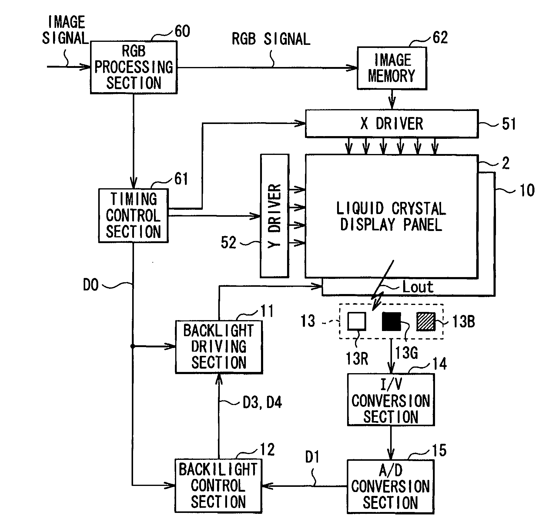
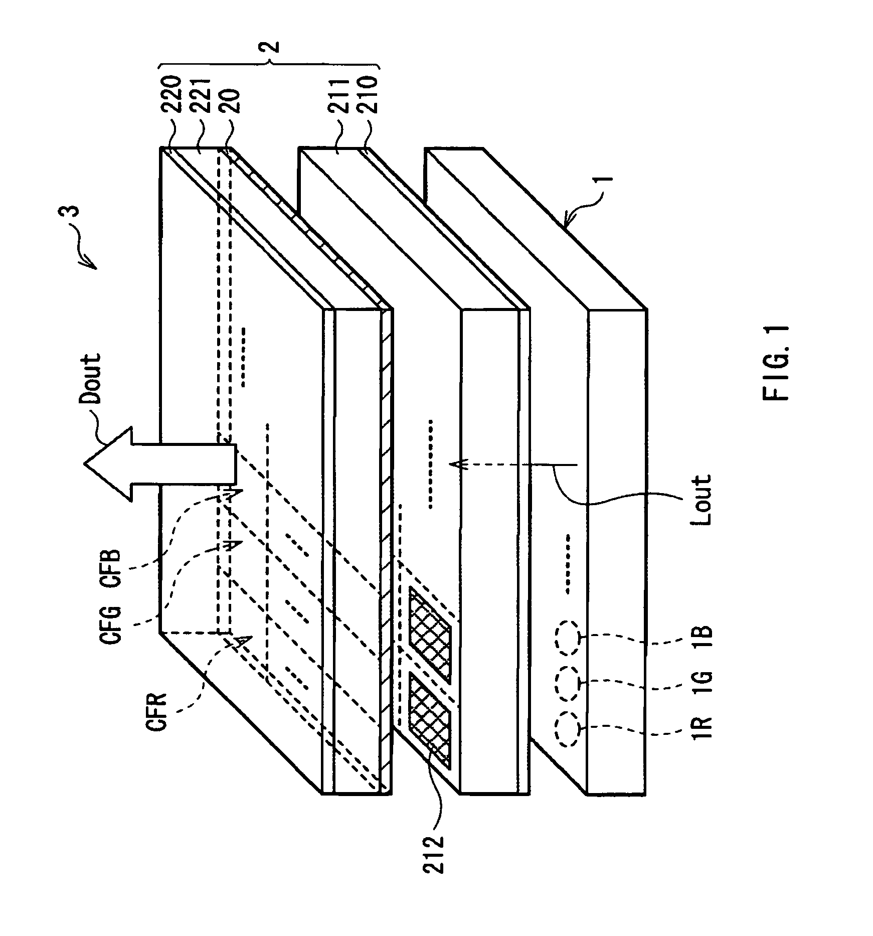
[0029]FIG. 1 shows the whole configuration of an image display system (a liquid crystal display 3) according to an embodiment of the invention. The liquid crystal display 3 is a so-called transmissive liquid crystal display emitting transmitted light as display light Dout, and includes a backlight system 1 as a light source device according to an embodiment of the invention and a transmissive liquid crystal display panel 2. A method of displaying an image according to an embodiment of the invention is embodied by an image display system according to the embodiment, and will be also described below.

[0030]The liquid crystal display panel 2 includes a transmissive liquid crystal layer 20, a pair of substrates between which the liquid crystal layer 20 is sandwiched, that is, a TFT (Thin Film Transistor) substrate 211 as a substrate on a side closer to the backlight system 1 and a facing...


PUM

PropertyMeasurementUnit
luminanceaaaaaaaaaa
color temperatureaaaaaaaaaa
color reproducibilityaaaaaaaaaa

Abstract

A light source system includes: a light source having a plurality of lighting sections each including one or more light-emitting diodes and controllable independently of one another; a light-sensing device detecting light from the light source in which the lighting sections are allowed to illuminate independently of one another; and a light source control means for controlling the light source by changing at least light emission intensity of each lighting section on the basis of a detected light amount, wherein the light source control means adjusts light emission currents in each lighting section in consideration of variation, among the plurality of lighting sections, in light emission characteristics showing a relationship between light emission currents flowing through the light-emitting diodes in a lighting section that illuminates and the detected light amount, thereby the light source control means controls the light emission intensity of each lighting section.

Description

CROSS REFERENCES TO RELATED APPLICATIONS[0001]The present invention contains subject matter related to Japanese Patent Application JP 2007-340962 filed in the Japanese Patent Office on Dec. 28, 2007, the entire contents of which being incorporated herein by reference.BACKGROUND OF THE INVENTION[0002]1. Field of the Invention[0003]The present invention relates to a light source system used as, for example, a backlight source of a liquid crystal display, and a display using the light source system.[0004]2. Description of the Related Art[0005]In recent years, flat panel displays as typified by liquid crystal TVs and plasma display panels (PDPs) have become a trend, and among them, most of mobile displays are liquid crystal displays, and precise color reproducibility is desired in the mobile displays. Moreover, as backlights for liquid crystal panels, CCFLs (Cold Cathode Fluorescent Lamps) using fluorescent tubes are mainstream; however, mercury-free light sources are environmentally de...

Claims


Application Information

Patent Timeline
Patent Type & Authority Applications(United States)
IPC IPC(8): G09G3/36G02F1/133G02F1/13357H01L33/00H05B37/02
CPCG09G3/3413G09G3/3426G09G2310/0237G09G2360/145G09G2320/064G09G2320/0666G09G2320/0233
Inventor KATSU, YOSHIHIRO
Owner SONY CORP
Why Eureka
Try Eureka