Noise filter

a noise filter and noise technology, applied in the field of noise filters, can solve the problems that the conventional noise filter has difficulty in appropriately suppressing the common mode voltage in the low frequency band, and achieve the effect of effectively suppressing the common mode voltag

Inactive Publication Date: 2015-09-08
TOYOTA IND CORP
View PDF7 Cites 12 Cited by
  • Summary
  • Abstract
  • Description
  • Claims
  • Application Information

AI Technical Summary

Benefits of technology

[0017]The aforementioned noise filter makes it possible to more effectively carry out the suppression of the common mode voltage by the Y capacitors.

Problems solved by technology

For this reason, the conventional noise filter has had difficulty in appropriately suppressing a common mode voltage in a low frequency band.

Method used


Image

  • Noise filter
  • Noise filter
  • Noise filter

Examples


embodiment

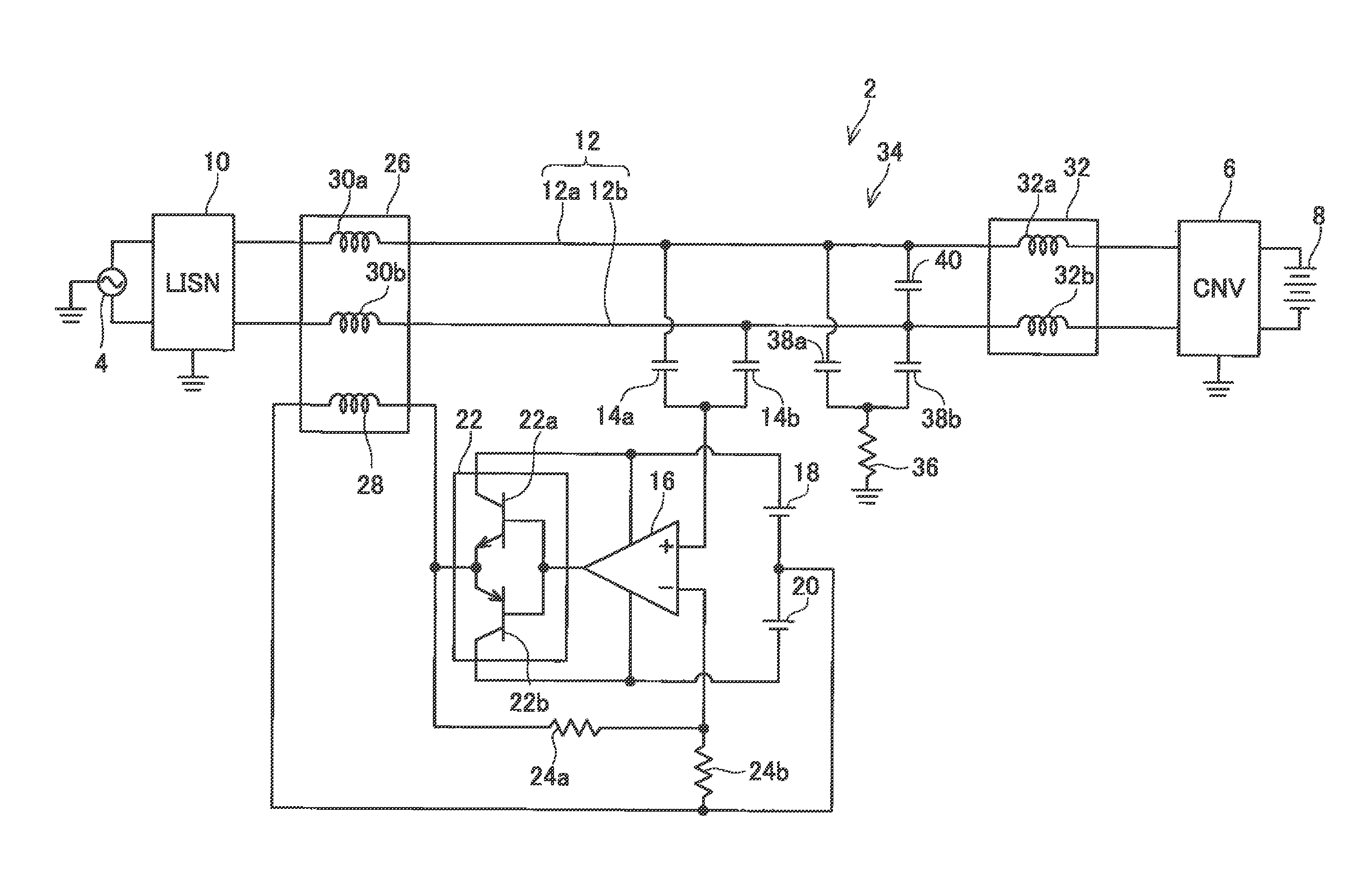
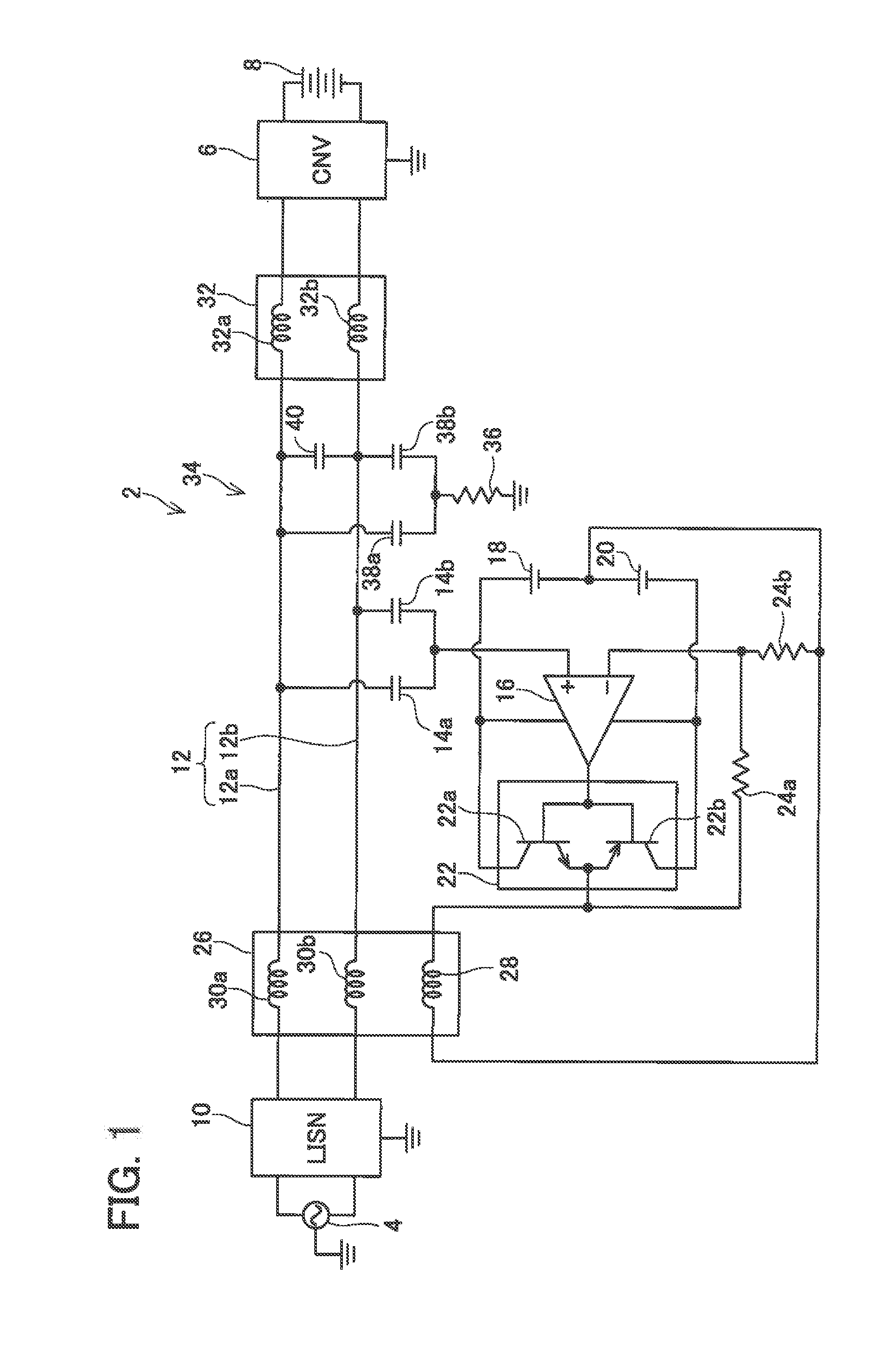
[0022]FIG. 1 shows a circuit configuration of a noise filter 2 according to an embodiment of the present invention. A noise filter 2 of the present embodiment suppresses common mode noise that is generated on the side of a commercial system due to operation of an electric power converter 6 connected to an AC power supply 4 of the commercial system. In the present embodiment, the electric power converter 6 is a voltage PWM inverter containing switching elements such as IGBTs. The electric power converter 6 converts AC power supplied from the AC power supply 4 into DC power and supplies the DC power to a battery 8.

[0023]An LISN (Line Impedance Stabilization Network) 10 is connected to the AC power supply 4. The LISN 10 and the electric power converter 6 are connected to each other via cables 12. The cables 12 include a positive cable 12a and a negative cable 12b.

[0024]One end of a detecting capacitor 14a is connected to the positive cable 12a. One end of a detecting capacitor 14b is ...


PUM


Abstract

A noise filter disclosed herein is configured to suppress a common mode voltage that is generated in cables connected to an electric power converter. The noise filter includes: detecting capacitors connected to the cables, respectively, and configured to detect the common mode voltage; an operational amplifier having a positive input terminal via which the common mode voltage detected by the detecting capacitors is inputted; an emitter follower circuit having an input terminal connected to an output terminal of the operational amplifier and having an output terminal connected to a negative input terminal of the operational amplifier; and a transformer configured to apply a compensating voltage to each of the cables by applying a voltage at the output terminal of the emitter follower circuit to each of the cables in opposite phase.

Description

CROSS-REFERENCE TO RELATED APPLICATION[0001]This application claims priority to Japanese Patent Application No. 2014-041757 filed on Mar. 4, 2014, the contents of which are hereby incorporated by reference into the present application.TECHNICAL FIELD[0002]The present specification relates to a noise filter.DESCRIPTION OF RELATED ART[0003]JP2010-57268A discloses a noise filter configured to suppress a common mode voltage that is generated in cables connected to an electric power converter. The noise filter includes: detecting capacitors connected to the cables, respectively, and configured to detect the common mode voltage; an emitter follower circuit having an input terminal via which the common mode voltage detected by the detecting capacitors is inputted; and a transformer configured to apply a compensating voltage to each of the cables by applying a voltage at an output terminal of the emitter follower circuit to each of the cables in opposite phase.BRIEF SUMMARY OF INVENTION[000...

Claims


Application Information

Patent Timeline
Patent Type & Authority Patents(United States)
IPC IPC(8): H03H5/00H03H11/12
CPCH03H11/126H03H7/427H03H11/1213H02M1/123
Inventor ISHIHARA, YOSHIAKIYAMAZAKI, KAZUJIKIKUCHI, NAOTOWATANABE, YOSHITOSHI
Owner TOYOTA IND CORP
Why Eureka
Try Eureka