
Joint Replacement And In Situ Gauge System

a gauge system and joint technology, applied in the field of joint replacement in situ gauge system, can solve the problems of non-uniform displacement, uniform displacement, etc., and achieve the effect of reducing operating time and trauma to the patient, and assessing the range of motion

Inactive Publication Date: 2020-12-31
DUGGAN INNOVATIONS LLC
View PDF0 Cites 0 Cited by
  • Summary
  • Abstract
  • Description
  • Claims
  • Application Information

AI Technical Summary

Benefits of technology

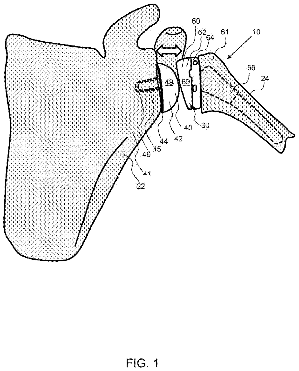
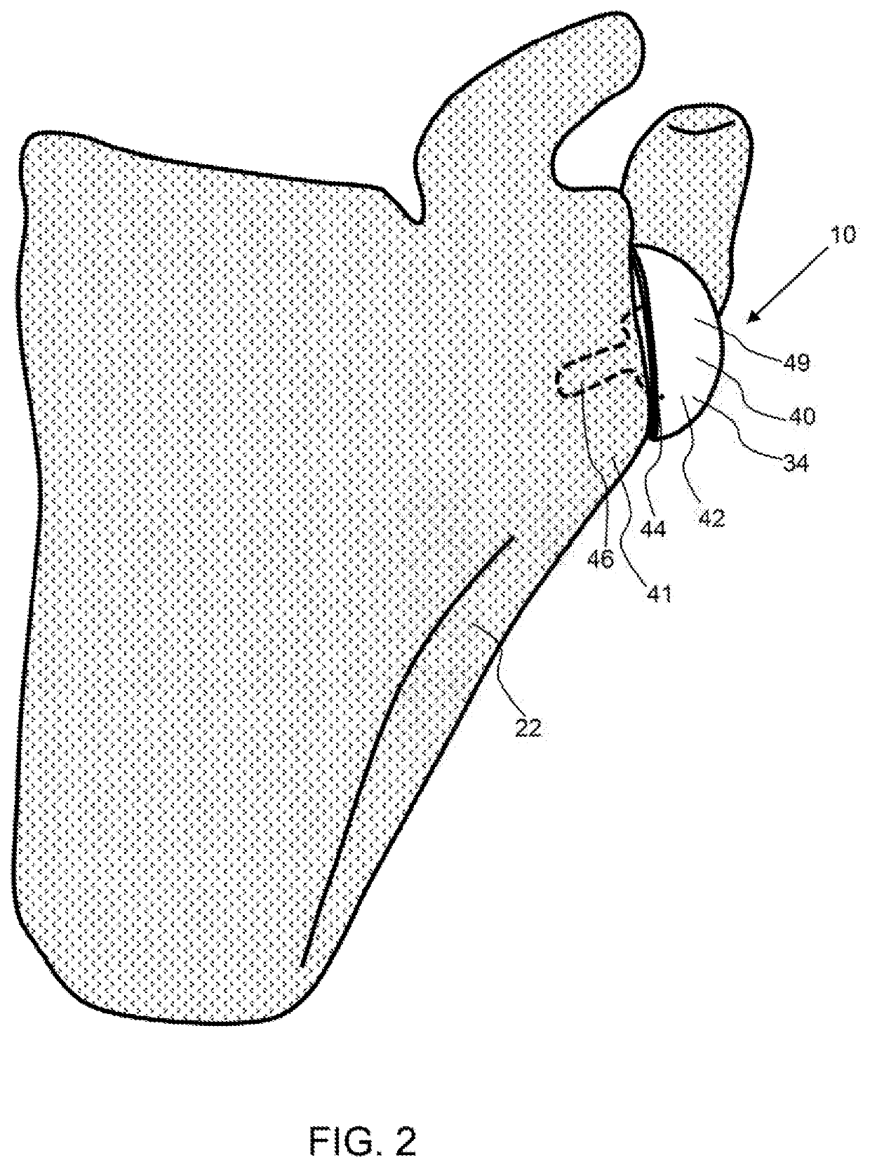
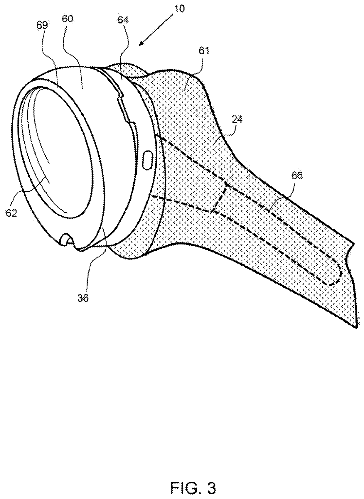
The invention is a joint replacement in situ gauge system that enables a surgeon to apply a known amount of distraction force to measure the appropriate spacing between two sides of a joint. This system reduces the need for iterative trials of implant components, reduces operating time, and trauma to the patient. The system includes a gauge component that may be molded to the shape of either a convex or concave component of the joint replacement. The gauge component has a displacement device that may be inflated with a fluid to determine the proper spacing between the components. The system also includes a scale to indicate the proper size of the implant component. The effect of the invention is to provide a more precise and streamlined joint replacement process.

Problems solved by technology

With the pressure or force set to a desired level for each of the displacement devices, the spacing or displacement may be non-uniform.
This non-uniform displacement may be required for proper load across the joint and to reduce wear and pain.

Method used


Image

  • Joint Replacement And In Situ Gauge System
  • Joint Replacement And In Situ Gauge System
  • Joint Replacement And In Situ Gauge System

Examples


Embodiment Construction

[0032]As used herein, the terms “comprises,”“comprising,”“includes,”“including,”“has,”“having” or any other variation thereof, are intended to cover a non-exclusive inclusion. For example, a process, method, article, or apparatus that comprises a list of elements is not necessarily limited to only those elements but may include other elements not expressly listed or inherent to such process, method, article, or apparatus. Also, use of “a” or “an” are employed to describe elements and components described herein. This is done merely for convenience and to give a general sense of the scope of the invention. This description should be read to include one or at least one and the singular also includes the plural unless it is obvious that it is meant otherwise.

[0033]Certain exemplary embodiments of the present invention are described herein and are illustrated in the accompanying figures. The embodiments described are only for purposes of illustrating the present invention and should not...


PUM


Abstract

A joint replacement in situ gauge system enables a surgeon to measure the appropriate spacing between the two sides of a joint, a convex component and a concave component. A replacement in situ gauge system includes a gauge component to measure the pressure and / or displacement of one joint component with respect to the mating component. A gauge component utilizes a displacement device that displaces the convex or concave component to determine a proper spacing for an implant component. The displacement component may be a bladder that is inflated with a fluid and a gauge may measure the pressure of the bladder through a range of motion. A scale may be used to measure physical displacement. The gauge component may be configured in the convex and / or concave components of the system. The gauge component may be removed and then an implant component may be implanted.

Description

CROSS REFERENCE TO RELATED APPLICATIONS[0001]This application claims the benefit of priority to U.S. provisional patent application No. 62 / 664,253, filed on Apr. 29, 2018; the entirety of which is hereby incorporated by reference herein.BACKGROUND OF THE INVENTIONField of the Invention[0002]The invention relates to a joint replacement in situ gauge system and a method of using the gauge system in a joint replacement procedure.Background[0003]Joint replacement surgery frequently requires the implant of a ball component into a socket, or more generally, a convex component into a concave component. When replacing a convex and / or a concave component of a joint, proper alignment and displacement of these components with respect to each other is critical to enable a full range of motion. In an exemplary embodiment, a convex component having a convex, or curved surface such as a radiused surface including a spherical surface for example, is attached to a first bone. A concave component hav...

Claims


Application Information

Patent Timeline
Patent Type & Authority Applications(United States)
IPC IPC(8): A61F2/46
CPCA61F2002/4661A61F2002/4658A61F2002/30548A61F2002/30584A61F2/461A61F2002/30131A61F2/4612A61F2/4657A61F2002/4666A61B5/4528A61B5/1036A61B5/6878A61B5/1076A61F2/4684A61F2/40A61F2/38A61F2002/4085A61F2002/4022
Inventor DUGGAN, BRIAN THOMASNACKARD, KEVIN JASON
Owner DUGGAN INNOVATIONS LLC
Learn More