Apparatuses and method for maskless mesoscale material deposition

a technology of mesoscale material and mask, applied in the direction of liquid/solution decomposition, chemical coating, instruments, etc., can solve the problems of limiting the application of microelectronics, thin film and thin film deposition processes are well-developed

Inactive Publication Date: 2006-05-16
OPTOMEC DESIGN CO
View PDF92 Cites 214 Cited by
  • Summary
  • Abstract
  • Description
  • Claims
  • Application Information

AI Technical Summary

Benefits of technology

[0011]It is an object of the present invention to provide a precision aerosol jetter for high resolution, maskless, mesoscale material deposition of liquid and particle suspensions in patterns. It is another object to provide a precision aerosol jetter that deposits electronic and biological materials with patterns in the range from about 10 microns to as large as several millimeters, while being relatively free of clogging and depositing on the orifice walls with the use of a sheath gas. It is another object to provide a precision aerosol jetter that uses aerodynamic focusing to deposit a pattern onto a planar or non-planar substrate without the use of masks. It is a further object to provide post-processing treatment of the substrate thermally or photochemically to achieve physical and / or electrical properties near that of a bulk material.

Problems solved by technology

Thick film and thin film processes for deposition of electronic structures are well-developed, but have limitations due to high processing temperatures or the need for expensive masks and vacuum chambers.
Thus, the high resistivity of ink jetted conductive polymers places limitations on microelectronic applications.

Method used


Image

  • Apparatuses and method for maskless mesoscale material deposition
  • Apparatuses and method for maskless mesoscale material deposition
  • Apparatuses and method for maskless mesoscale material deposition

Examples


embodiment

PREFERRED EMBODIMENT

1. Aerosolization

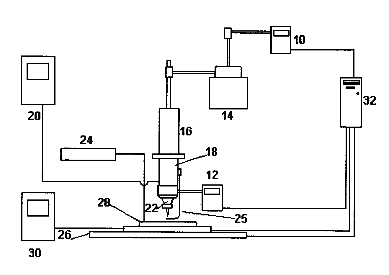
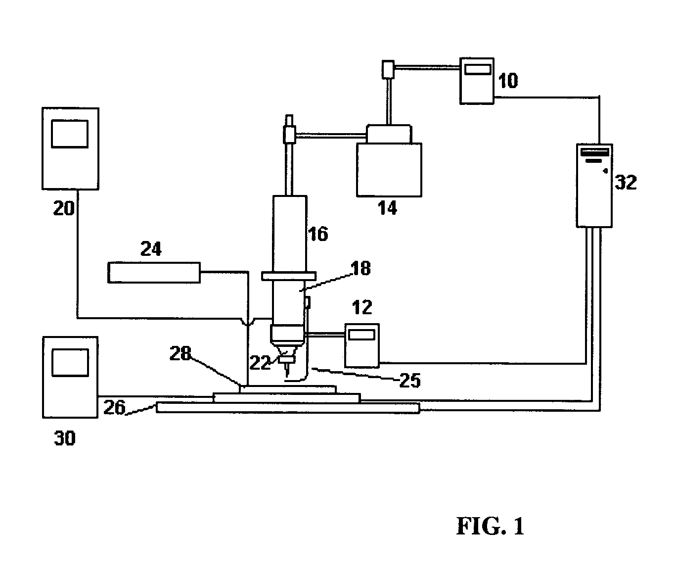
[0029]FIG. 1 shows the preferred M3D™ apparatus. Like reference numerals are used to describe the same elements throughout the various figures in order to create parity and for convenience of illustration. The M3 D™ process begins with the aerosolization of a solution of a liquid molecular precursor or suspension of particles. The solution may also be a combination of a liquid molecular precursor and particles. As by way of example, and not intended as limiting, precursor solutions may be atomized using an ultrasonic transducer or pneumatic nebulizer 14, however ultrasonic aerosolization is limited to solutions with viscosities of approximately 1–10 cP. The fluid properties and the final material and electrical properties of the deposit are dependent on the precursor chemistry. Aerosolization of most particle suspensions is performed using pneumatics, however ultrasonic aerosolization may be used for particle suspensions consisting of either smal...


PUM

PropertyMeasurementUnit
feature sizeaaaaaaaaaa
viscosityaaaaaaaaaa
sizesaaaaaaaaaa

Abstract

Apparatuses and processes for maskless deposition of electronic and biological materials. The process is capable of direct deposition of features with linewidths varying from the micron range up to a fraction of a millimeter, and may be used to deposit features on substrates with damage thresholds near 100° C. Deposition and subsequent processing may be carried out under ambient conditions, eliminating the need for a vacuum atmosphere. The process may also be performed in an inert gas environment. Deposition of and subsequent laser post processing produces linewidths as low as 1 micron, with sub-micron edge definition. The apparatus nozzle has a large working distance—the orifice to substrate distance may be several millimeters—and direct write onto non-planar surfaces is possible.

Description

CROSS-REFERENCE TO RELATED APPLICATIONS[0001]This application is a continuation-in-part application of the following U.S. Patent Applications:[0002]U.S. patent application Ser. No. 09 / 574,955, entitled “Laser-Guided Manipulation of Non-Atomic Particles”, to Michael J. Renn, et al., filed on May 19, 2000 now U.S. Pat. No. 6,823,124, which was a continuation application of U.S. patent application Ser. No. 09 / 408,621, entitled “Laser-Guided Manipulation of Non-Atomic Particles”, to Michael J. Renn, et al., filed on Sep. 30, 1999 now abandoned, which claimed the benefit of U.S. Provisional Patent Application Ser. No. 60 / 102,418, entitled “Direct-Writing of Materials by Laser Guidance”, to Michael J. Renn, et al., filed on Sep. 30, 1998;[0003]U.S. patent application Ser. No. 09 / 584,997, entitled “Particle Guidance System”, to Michael J. Renn, filed on Jun. 1, 2000 now U.S. Pat. No. 6,636,676, which was a continuation-in-part application of U.S. patent application Ser. No. 09 / 574,955;[000...

Claims


Application Information

Patent Timeline
Patent Type & Authority Patents(United States)
IPC IPC(8): B05C11/06G02B6/00
CPCB05D1/02B05D5/12C23C18/14H05K3/1241B05D3/06C23C18/06B05D3/068B05D5/00C23C18/143
Inventor RENN, MICHAEL J.KING, BRUCE H.ESSIEN, MARCELINOHUNTER, LEMNA J.
Owner OPTOMEC DESIGN CO
Why Eureka
Try Eureka