In-mold coating injection inlet flow control

a technology of inlet flow control and inlet flow, which is applied in the direction of cellulosic plastic layered products, other domestic articles, synthetic resin layered products, etc., can solve the problems of difficult or impossible to produce an in-mold coated article which has been properly or fully coated to desired specifications

Inactive Publication Date: 2006-05-16
OMNOVA SOLUTIONS INC
View PDF56 Cites 20 Cited by
  • Summary
  • Abstract
  • Description
  • Claims
  • Application Information

AI Technical Summary

Benefits of technology

[0016]Advantageously, it has been found that the flow of in-mold coating over an article can be effectively controlled, whereby the coating can be channeled or routed so that the coating on the substrate surface conforms to design specifications. The in-mold coatings are preferably channeled by providing the substrate with areas of varying thickness or depth below the surface to be coated. It has been found that substrate areas of greater depth promote in-mold coating flow relative to less thick areas. The present invention also teaches a method for controlling the thickness of an in-mold coating on a substrate.
[0018]A further object of the present invention is to eliminate the need of applying additional paint or other surface treatment coatings to a surface of a pre-formed work piece.
[0019]Yet another object of the present invention is to provide a work piece having an appearance in-mold coating thereon, which has paint-like properties, such as high gloss, hardness, good adhesion and good weatherability.
[0020]A further object of the present invention is to provide a work piece having an in-mold coating thereon, which has good flow and coverage during molding, good adhesion, uniform color, durability, weather resistance, good surface qualities, and good paintability.
[0021]In one embodiment of the present invention, a molded article is provided with an area of increased relative thickness at the location of in-mold coating injection in order to encourage or promote in-mold coating flow.
[0023]Still another embodiment of the present invention involves providing a molded article or substrate with an in-mold coating containment flange which acts as a barrier and prevents the in-mold coating from leaking or seeping out of the mold cavity. The in-mold coating containment flange extends substantially completely around the perimeter of a coated molded substrate surface.

Problems solved by technology

Molded substrates often have complex designs or configurations and heretofore, it has been difficult or impossible to produce an in-mold coated article which has been properly or fully coated to desired specifications.

Method used


Image

  • In-mold coating injection inlet flow control
  • In-mold coating injection inlet flow control
  • In-mold coating injection inlet flow control

Examples


example 1

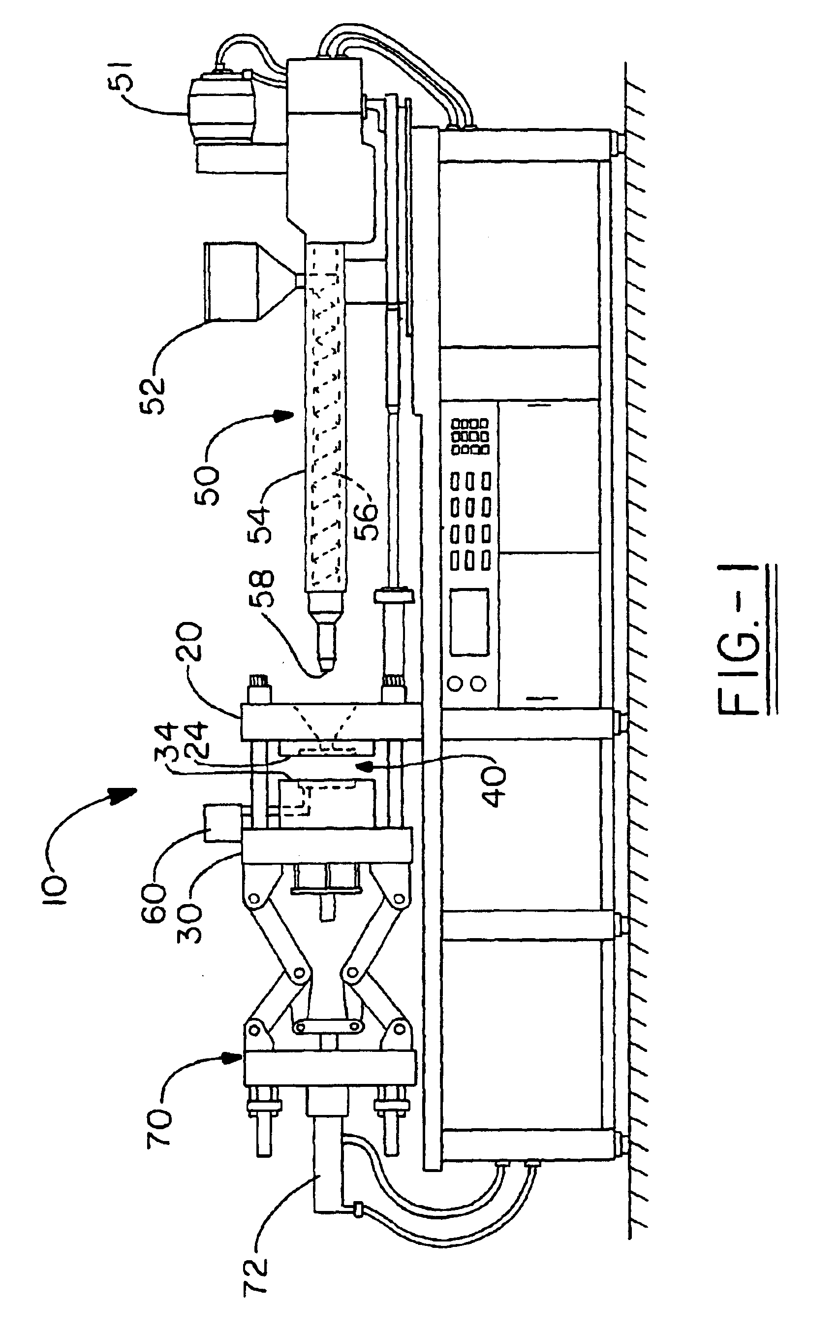
[0088]A mold used to produce the plaque 200 shown in FIG. 9 was made. The mold cavity width is 12.0 inches. The mold cavity length is 20.5 inches. The mold has a hydraulic mold gate located in the center of the cavity for injection of a substrate. The mold has a tapered tab for the introduction of the IMC onto the part surface. The tab is located at the edge portion of the mold. The tab and Section A have thicknesses of 120 mils. Section B is 100 mils thick. Section C is 080 mils thick. Section D is 060 mils thick. As shown in FIG. 9, the plaque has four panels in a horizontal plane on the left side of the part and four panels in a vertical plane on the right side of the part. The panels on the horizontal plane on the right side of the part measure 6.0 inches long and 5.125 wide. The panels on the vertical plane measure 1.50 inches wide and 20.5 inches long. The plaque does not have an in-mold coating containment flange. The mold was placed in an 850 ton Cincinnati Milacron Vista in...

example 2

[0091]FIG. 10 shows a thermoplastic article with a variety of substrate (thermoplastic) thicknesses. It was shown through experimentation that in-mold coating flow is influenced by the substrate thickness. The example parts were generated using a 50-ton injection molding machine, a 6-inch square steel mold cavity fitted with an IMC injection nozzle. The substrate material was a PET thermoplastic and the in-mold coating was OMNOVA's Stylecoat® IMC. The mold temperature was 250° F. with a 30 second delay time prior to IMC injection.

[0092]In FIG. 10, sections E, F, and G are representations of varying part thickness as shown by the chart below. Section H represents the in-mold coating tab design utilizing a thicker middle section which facilitates an in-mold coating flow channel at the in-mold coating nozzle tip site. Section I represents the thin sectioned containment flange.

[0093]The overall objective in designing a mold with thin and thick sections is to preferential channel the in-...


PUM

PropertyMeasurementUnit
pressureaaaaaaaaaa
thicknessaaaaaaaaaa
thicknessaaaaaaaaaa

Abstract

Molded articles or substrates having an in-mold coating thereon are disclosed. The in-mold coated substrates are produced by a method wherein the flow of the in-mold composition onto the substrate can be selectively controlled. The molded articles can be preferentially coated in desired or predetermined areas with in-mold coating compositions by controlling the thickness or depth of various sections of the substrate. The present invention provides a molded article with an area of increased relative thickness at the location of in-mold coating injection to encourage or promote in-mold coating flow.

Description

CROSS REFERENCE[0001]This application is a continuation-in-part of prior application Ser. No. 10 / 045,481, filed Oct. 22, 2001, entitled “Selectively Controlling In-Mold Coating Flow.”FIELD OF THE INVENTION[0002]The present invention relates to a method for coating a molded article or thermoplastic substrate with an in-mold composition, wherein the flow and thus the thickness of the in-mold composition onto the substrate can be selectively controlled. Importantly, desired areas of molded articles can be preferentially coated with in-mold coating compositions by controlling the thickness or depth of various sections of the substrate. Advantageously, the method of the present invention can be utilized to mold articles of relatively complex shape or design which have an in-mold coating thereon having a uniform or desired appearance.[0003]In one embodiment of the present invention, a molded article is provided with an area of increased relative thickness at the location of in-mold coatin...

Claims


Application Information

Patent Timeline
Patent Type & Authority Patents(United States)
IPC IPC(8): B32B27/36B05D7/02B05D7/24B29C37/00B29C45/00B29C45/16B29C45/26B29C67/24B29K101/12B29K279/00B32B27/08
CPCB29C37/0028B29C45/1679B32B27/08Y10T428/24612B29C45/0046B29C67/246B29C2045/1687B29K2023/00B29K2025/00B29K2027/06B29K2059/00B29K2067/00B29K2069/00B29L2031/3005Y10T428/24777B29C37/0053Y10T428/31507
Inventor STRAUS, ELLIOTT J.
Owner OMNOVA SOLUTIONS INC
Why Eureka
Try Eureka