
Racing vehicle position indication system and method

a technology of position indication system and racing vehicle, which is applied in the direction of direction finders using radio waves, instruments, sport apparatus, etc., can solve the problems of difficult for spectators to determine which car is leading a race, requires spectators to look away from the race, and becomes quite expensiv

Active Publication Date: 2006-05-16
LEADING LIGHTS LLC
View PDF18 Cites 13 Cited by
  • Summary
  • Abstract
  • Description
  • Claims
  • Application Information

AI Technical Summary

Benefits of technology

[0008]Another object of the present invention is to provide a position indicating system and method for visually indicating a racing vehicle's current position in the field which automatically updates each vehicle's position in the field as the race progresses.
[0009]A further object of the present invention is to provide a position indicating system and method for visually indicating a racing vehicle's current position in the field which is easily retrofitted to existing racing vehicles and racetracks.
[0010]Yet another object of the present invention is to provide a position indicating system and method for visually indicating a racing vehicle's current position in the field which is operated automatically by a racetrack's existing timing system.

Problems solved by technology

These races often require the competitors to complete multiple laps around the track and frequently require pit stops for refueling and repairs during the race.
The length of races and necessity of pit stops often makes it difficult for spectators to determine which car is leading a race at any given moment.
This inability to determine a particular car's current position in the field leads to frustration, especially in the casual fan.
One disadvantage of this solution, however, is that it requires spectators to look away from the race to view the board.
Another disadvantage of this solution is that it requires the construction and maintenance of multiple boards at various locations around a track so that all spectators maybe within viewing distance of a board.
At larger race venues this can become quite expensive.

Method used


Image

  • Racing vehicle position indication system and method
  • Racing vehicle position indication system and method
  • Racing vehicle position indication system and method

Examples


Embodiment Construction

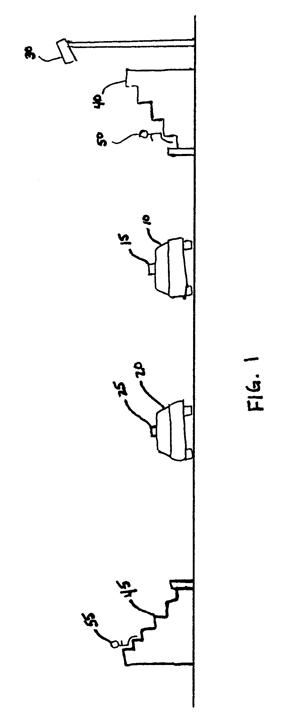
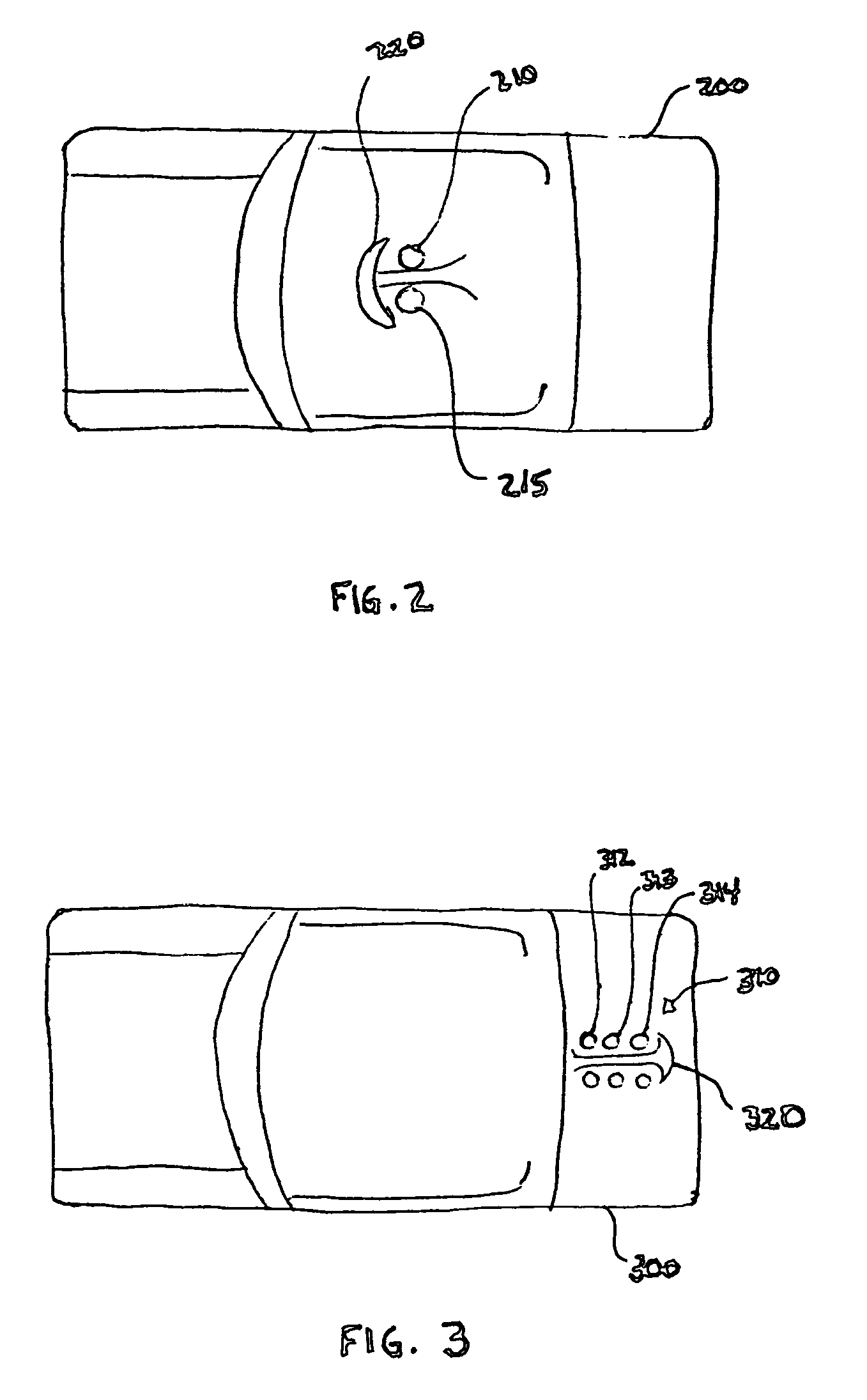
[0022]For the purposes of promoting understanding of the principles of the invention, reference will now be made to the embodiment illustrated in the drawings and specific language will be used to describe the same. It will nevertheless be understood that no limitation of the scope of the invention is hereby intended and alterations and modifications in the illustrated device, and further applications of the principles of the present invention as illustrated herein being contemplated as would normally occur to one skilled in the art to which the invention relates.

[0023]The present invention relates to a system and method for visually indicating a racing vehicle's current position in a field of vehicles during a race. To aid in the explanation of the present invention, the following description will refer only to racecars. This is for illustrative purposes only and is not a limitation on the scope of the present invention. It is understood that the present invention may be practiced ...


PUM


Abstract

A system for indicating race position to spectators of a race, includes lights on the race participants that are configured to provide visual displays to the spectators indicating the position of the respective racer. The race participants also carry a receiver and a controller for receiving a signal indicating race position and selecting the appropriate visual display based on the received signal. The visual display can be a series of lights, such as linear arrays of LEDs, where the color, number, pattern and / or position of the lights indicates race position. The system can also be used to highlight selected racers of interest, for example in conjunction with information being relayed over the public address system of the racetrack.

Description

RELATED APPLICATIONS[0001]This application claims the benefit of U.S. Provisional Application Ser. No. 60 / 424,422, filed Nov. 7, 2002, the disclosure of which is incorporated by reference.FIELD OF THE INVENTION[0002]The present invention relates generally to a system and method for indicating the current position in the field of a racecar and more specifically to indicators allowing spectators to discern a particular car's position in the field without having to divert their attention from the race.BACKGROUND OF THE INVENTION[0003]Automobile racing has become one of the most popular spectator sports in the world. Formal automobile racetracks range from small, dirt covered ovals to large, paved surfaces more than a mile in length. These races often require the competitors to complete multiple laps around the track and frequently require pit stops for refueling and repairs during the race.[0004]The length of races and necessity of pit stops often makes it difficult for spectators to d...

Claims


Application Information

Patent Timeline
Patent Type & Authority Patents(United States)
IPC IPC(8): G08B23/00B60Q1/50
CPCB60Q1/50G06Q20/405G06Q20/227B60Q1/5035
Inventor FUGIT, DAVID K.
Owner LEADING LIGHTS LLC
Learn More