Range finder

a range finder and optical range technology, applied in the field of optical range finders or distance measuring devices, can solve the problems of measurement distance errors, affecting the distance b of the detecting device of the semiconductor chip, and the conventional techniques described above have various problems, so as to reduce the influence of thermal expansion and contraction of the optical casing, reduce the influence and reduce the effect of thermal expansion and contraction

Inactive Publication Date: 2006-05-16
FUJI ELECTRIC DEVICE TECH CO
View PDF6 Cites 22 Cited by
  • Summary
  • Abstract
  • Description
  • Claims
  • Application Information

AI Technical Summary

Benefits of technology

[0038]According to the present invention, the lens holder may have a circular hole and a long hole. The long hole is extended in a direction perpendicular to the line between the optical axes of the lenses (along the line connecting the bosses) Therefore, it is possible to reduce an influence of the thermal expansion and contraction of the optical casing in the direction on the lens holder.
[0039]According to the present invention, in the range finder, each of the first and second lenses may be made of a transparent resin and may have a reference boss and an absorbing boss. The lens holder may include circular reference holes and long absorbing holes on a line between the centers of the first and second lens holes. When the first and second lenses are attached to the first and second lens holes of the lens holder, the reference bosses are fixed to the circular reference holes with an elastic adhesive layer, and the absorbing bosses are moveably inserted into the long absorbing holes. In general, a lens made of a resin exhibits thermal expansion and contraction larger than that of a lens made of glass. Accordingly, the long absorbing holes and the absorbing bosses are provided for absorbing the thermal expansion and contraction of the resin lens relative to the lens holder, thereby reducing the thermal expansion and contraction within an acceptable range.
[0040]According to the present invention, in the range finder, the lens holder may have two holes on a bisector perpendicular to a line connecting centers of the first and second lens holes, and the optical casing may have two bosses inserting into the holes. The two bosses of the optical casing are fitted into the holes of the lens holder, so that the optical casing is fixed to the lens holder. The lens holder is positioned using the bosses of the optical casing as reference. Accordingly, the semiconductor chip does not move relative to the lens holder with a centerline connecting the bosses as the reference. As a result, it is possible to reduce an influence of the thermal expansion and contraction of the optical casing on the measured distance error.
[0041]According to the present invention, in the range finder, the lens holder may include two holes on a bisector perpendicular to a line between centers of the first circular reference hole at a side of the first lens and the second circular reference hole at a side of the second lens. The optical casing may have two bosses for inserting into the holes. The two bosses of the optical casing are fitted into the holes of the lens holder, so that the optical casing is fixed to the lens holder. The optical casing is fixed to the lens holder at the bisector perpendicular to the line between the first circular reference hole at the side of the first lens hole (reference boss on the first lens) and the second circular reference hole at the side of the second lens hole (reference boss on the second lens). Accordingly, it is possible to balance between the thermal expansion and contraction of the lens holder and the thermal expansion and contraction of the first and second lenses at the optical axes of the first and second lenses. As a result, the optical axes of the first and second lenses equally move in the same direction, thereby reducing the measured distance error caused by the thermal expansion or contraction.
[0042]In the invention, the optical casing, the lens holder, and the first and second lenses are disposed at proper positions. Accordingly, when the temperature changes, the constituent parts are expanded or contracted in a balanced way by utilizing a difference among the coefficients of the thermal expansion of the materials of the optical casing, the lens holder and the lenses. Therefore, the displacements of the constituent parts are canceled out with each other, and the optical axes of the lenses move symmetrically in a lateral direction. Further, there is little difference in the thermal expansion and contraction between the lenses and the semiconductor chip, thereby eliminating measured distance error.
[0043]According to the present invention, the lens holder may have a circular hole and a long hole. The long hole is extended in a direction perpendicular to the line between the optical axes of the lenses (along the line connecting the bosses). Therefore, it is possible to reduce an influence of the thermal expansion or contraction of the optical casing in the direction on the lens holder.

Problems solved by technology

Therefore, when the lens distance b and the detecting device distance b change relatively, the displacements XL and XR from the reference points PO change, thereby causing the measured distance error.
On the other hand, the lens distance b of the lenses and the detecting device distance b of the semiconductor chips are seriously affected by the thermal expansion and contraction.
The conventional techniques described above have various problems.
Further, it is necessary to provide two range finders and a space for the two range finders inside the instrument such as a camera, thereby making the range finder not practical.
Accordingly, it is necessary to provide the temperature sensor and an extra circuit for receiving the temperature data, and to conduct the complicated correction control, thereby increasing cost, the number of electronic circuits and control operations.
However, it is difficult to completely eliminate the expansion or contraction of the lens.

Method used


Image

  • Range finder
  • Range finder
  • Range finder

Examples


first embodiment

[0096]The invention has been described above with reference to the The invention is not limited to the specific embodiment, and any changes and modifications are possible within the scope of the invention.

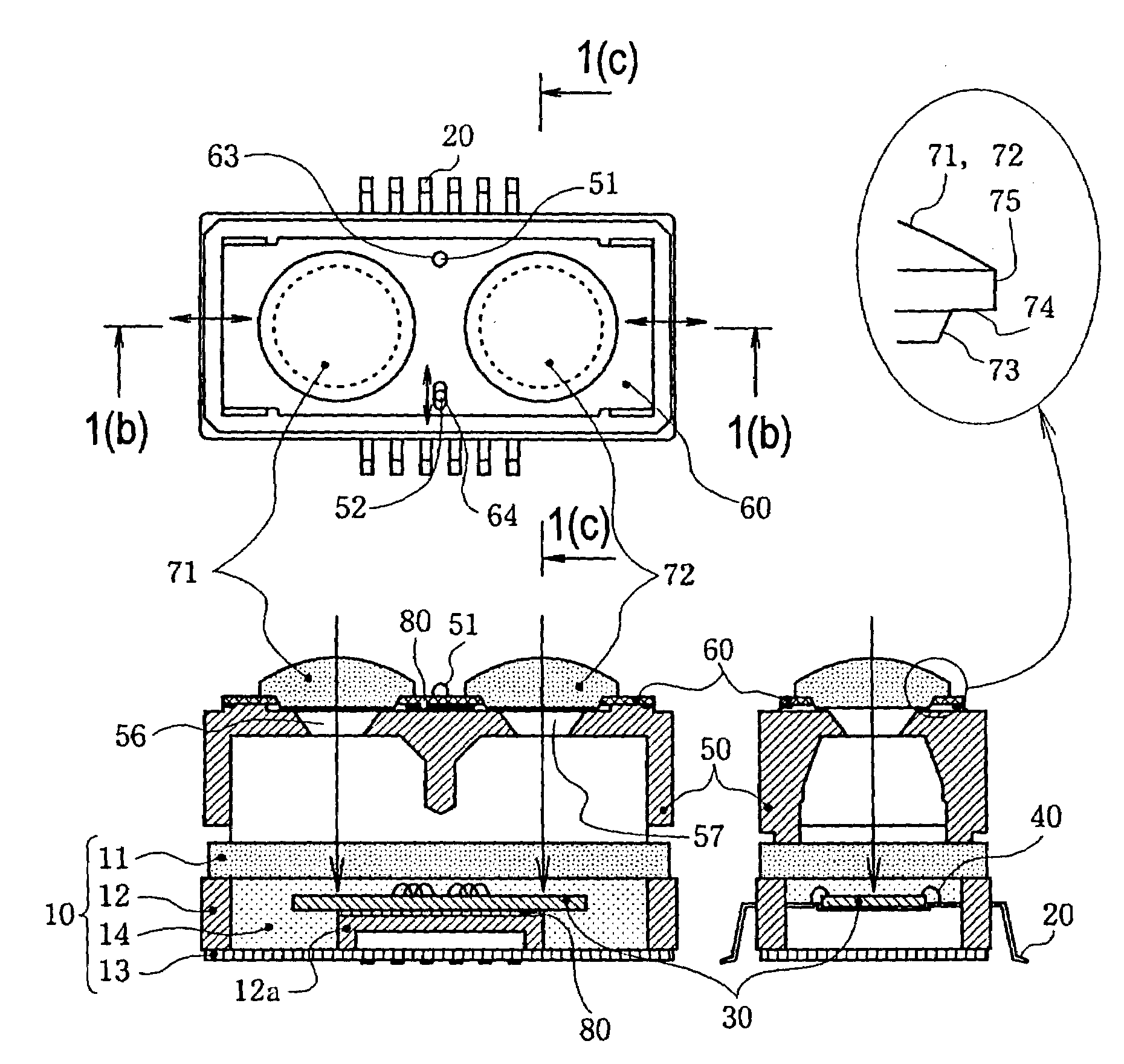
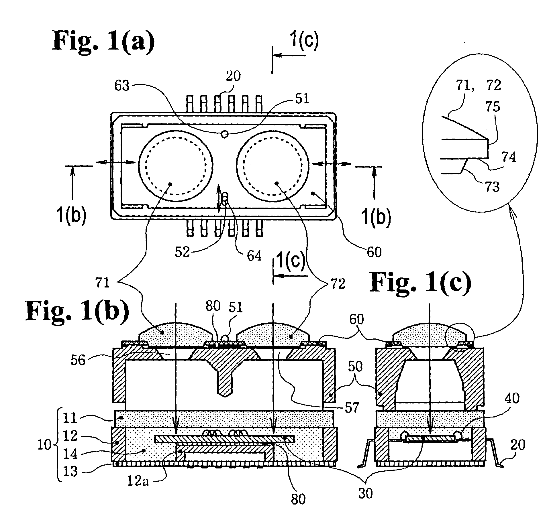
[0097]A second embodiment of the invention will be described next with reference to FIGS. 4(a) through 6. FIGS. 4(a) to 4(c) are views showing a range finder according to the second embodiment of the present invention, wherein FIG. 4(a) is a plan view thereof, FIG. 4(b) is a cross sectional view taken along line 4(b)—4(b) in FIG. 4(a), and FIG. 4(c) is a cross sectional view taken along line 4(c)—4(c) in FIG. 4(a). FIGS. 5(a) to 5(d) are views showing components of the range finder shown in FIGS. 4(a) to 4(c), wherein FIG. 5(a) is a plan view of a lens holder, FIG. 5(b) is a front view of a lens, FIG. 5(c) is a bottom view of the lens, and FIG. 5(d) is a side view of the lens. FIG. 6 is a plan view of the range finder for explaining an adhesion therein and thermal expansion and co...

second embodiment

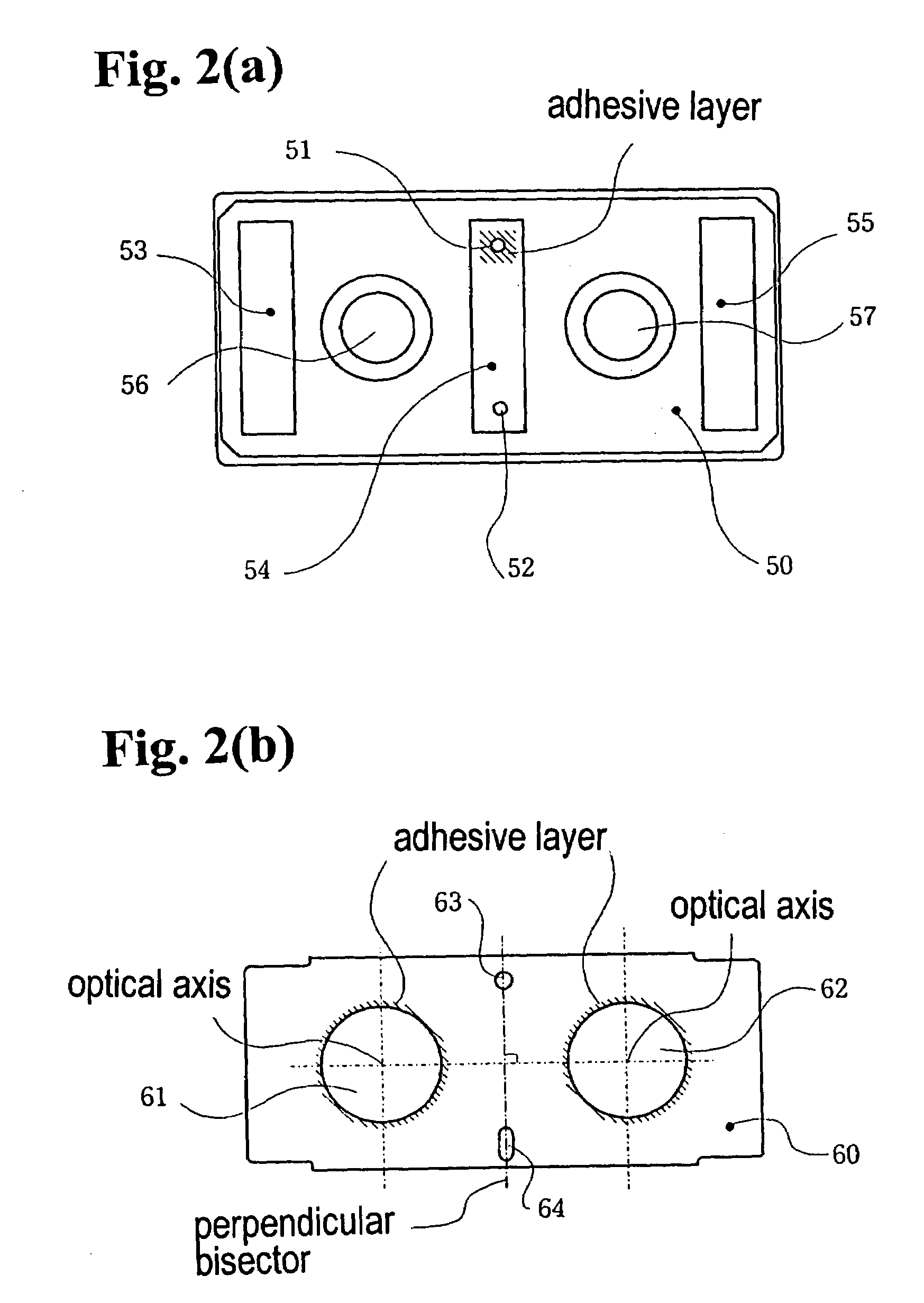
[0110]In the second embodiment, the circular reference holes 105 and long absorbing holes 106 are arranged on the extension of the line connecting the centers of the first and second lens holes 101 and 102 (line connecting the centers of the circular reference holes 105), and the long absorbing holes 106 extend along the extension of the line. When the lenses 111 and 112 rotate around the reference bosses 116 in the circular reference holes 105 due to the temperature change, the absorbing bosses 117 in the long absorbing holes 106 restrict the lenses 111 and 112. As a result, the displacement of the optical axes of the lenses 111 and 112 due to temperature change of the adhesive layers 80 is limited substantially to the line connecting the centers of the first and second lens holes 101 and 102 by the long absorbing holes 116 and the absorbing bosses 117. A change in the distance between the optical axes of the first and second lenses 111 and 112 is very small as compared with the le...

third embodiment

[0115]A third embodiment of the invention will be described with reference to FIGS. 7(a) through 9. FIGS. 7(a) to 7(c) are views showing a range finder according to the present invention, wherein FIG. 7(a) is a plan view thereof, FIG. 7(b) is a cross sectional view taken along line 7(b)—7(b) in FIG. 7(a), and FIG. 7(c) is a right side view of the range finder. FIGS. 8(a) and 8(b) are views showing components of the range finder shown in FIGS. 7(a) to 7(c), wherein FIG. 8(a) is a plan view of an optical casing, and FIG. 8(b) is a plan view of a lens holder. FIG. 9 is a diagram for explaining the principle of canceling the thermal expansion and contraction.

[0116]As shown in FIGS. 7(a) through 7(c), in the third embodiment, a range finder 3 includes the package 10, the leads 20, the semiconductor chip 30, the bonding wires 40, an optical casing 120, a lens holder 130, a pair of lenses 110, and the adhesive layers 80. The lenses 110 are two discrete lenses, namely a first lens 111 on th...


PUM


Abstract

A range finder includes a package, a semiconductor chip, an optical casing, a lens holder, a first lens, and a second lens. The first and second lenses are attached to the lens holder. The lens holder is formed of a material having a thermal expansion coefficient equal or close to that of the semiconductor chip. The range finder is constructed such that a distance between the two lenses and a distance between two light detecting sections on the semiconductor chip do not change significantly relative to each other due to the thermal expansion or contraction.

Description

BACKGROUND OF THE INVENTION AND RELATED ART STATEMENT[0001]The present invention relates to an optical range finder or distance measuring device used for a camera.[0002]An optical device provided in a camera uses a method such as an active method or a passive method for measuring a distance. In the active method, light is emitted toward an object, and a distance to the object is determined with triangulation. In the passive method, light irradiated from an object is detected, and a distance to the object is determined through a difference in phases of the light.[0003]The active method will be described below in detail. An active range finder includes a light emitting unit having a light emitting element such as a light emitting diode (LED), a light emitting lens, a light receiving lens, and a light receiving unit having a light detecting element such as a position sensitive detector (PSD). The light emitting unit emits light toward an object through the light emitting lens, and the ...

Claims


Application Information

Patent Timeline
Patent Type & Authority Patents(United States)
IPC IPC(8): G01C3/08G01B11/00G01C3/06G01S7/481G01S7/497G02B7/02G02B7/28G02B7/32G03B13/20G03B13/36
CPCG01C3/08G02B7/32G01S7/497G01S7/4813G01S17/48G03B13/20
Inventor YAMAMOTO, TOSHIOIZUMI, AKIO
Owner FUJI ELECTRIC DEVICE TECH CO
Why Eureka
Try Eureka