Device and method for the optical detection of objects

Inactive Publication Date: 2006-05-16
BAUMER ELECTRIC
View PDF6 Cites 7 Cited by
  • Summary
  • Abstract
  • Description
  • Claims
  • Application Information

AI Technical Summary

Benefits of technology

[0013]An advantage of the invention is the fact that the reflector may be large in comparison with the measuring beam and, therefore, a precise adjustment does not become necessary. The reflector may be a simple, for example white, object (e.g., made of ceramics, etc.). An accurate alignment of the angle of this part of the device is not necessary. A reflector, for example, may be completely or partially arranged around a light outlet opening of the light source and comprise solely one further opening for a light receiving means of the sensor.
[0014]Particularly advantageous for the function of the invention is the circumstance that the “mirror

Problems solved by technology

This method has the disadvantage that it does not work in case of reflective mirror-like surfaces because it is based on the diffuse scattering.
Here there is the difficulty, that these high-purity—and polished surfaces generate hardly any scattered light.
The disa

Method used


Image

  • Device and method for the optical detection of objects
  • Device and method for the optical detection of objects
  • Device and method for the optical detection of objects

Examples


Embodiment Construction

[0023]Initially, it is noted that in the In the Figures the same reference characters designate the same or analogous elements.

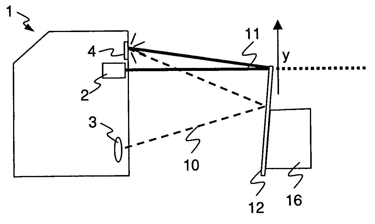
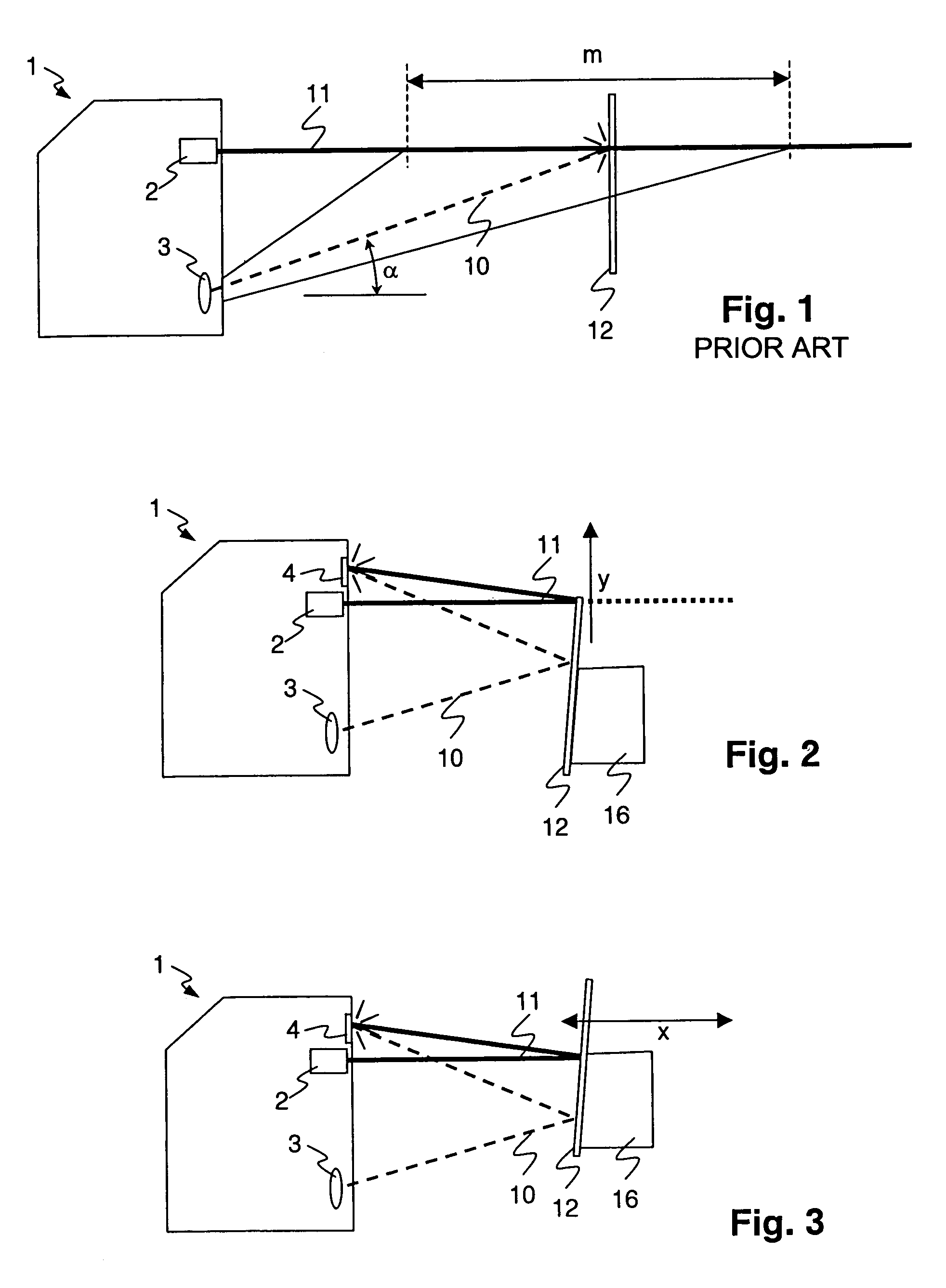
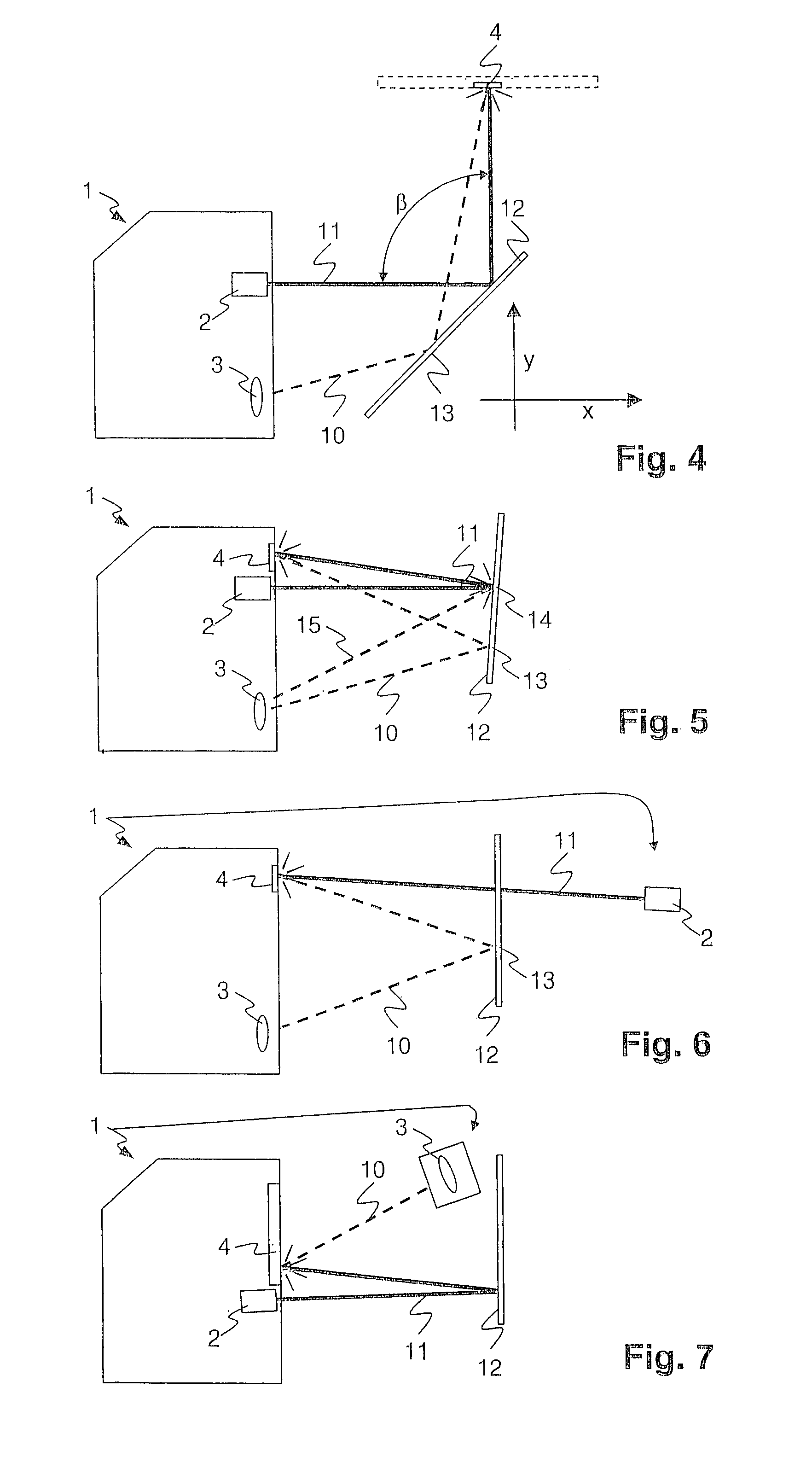
[0024]FIG. 2 illustrates an embodiment of the invention, which is able to be utilised, when the invention is to be used for the detection of the moving of the “mirror” into a defined field. An optical sensor 1 comprises a light source 2 for the generation of a laser beam or light beam 11 and a light receiving means. The light receiving means comprises a receiving lens system 3, light-sensitive elements of a known type, and integrated or external means of evaluation. With the means of evaluation, an angle of incidence of a light beam and, from it, a presence or a distance of an object are capable of being determined. The optical sensor 1 comprises a reflector 4 exhibiting diffuse reflection. In the application example under consideration, a movement of an article with a mirroring surface 12 into the light beam 11 is to be detected. For this purpose, the objec...


PUM


Abstract

A method and a device for the optical distance measurement and for the optical detection of objects with an at least partially specular reflective surface (12) wherein light through the specular reflective surface (12) and a diffuse scattering at a reflector (4) is directed to light receiving means and detected there.

Description

BACKGROUND OF THE INVENTION[0001]1. Field of the Invention[0002]The present invention is generally related to optically measuring distances and optically detecting objects and, more particularly, to a device and a method for optically measuring distances and optically detecting reflective surfaces.[0003]2. Description of Related Art[0004]One example of a conventional optical sensor 1 is illustrated in FIG. 1: A light beam 11 generated by a laser 2 impinges on an object 12 to be detected and is at least partially diffusely scattered there. Scattered light is received by a receiving lens system 3 at an angle α, which is dependent on the distance of the object from the sensor. The angle α is determined in the receiver. In correspondence with a maximum and a minimum determinable angle of incidence α, a measuring range m results, within which a distance of the object 12 is capable of being determined.[0005]This method has the disadvantage that it does not work in case of reflective mirro...

Claims


Application Information

Patent Timeline
IPC IPC(8): G01B11/14G01B11/02G01C3/08
CPCG01C3/085G01B11/026
Inventor MULLER, KLAUS
Owner BAUMER ELECTRIC
Why Eureka
Try Eureka