C-shaped combination capacitor assembly

a capacitor and combination technology, applied in the direction of electrolytic capacitors, fixed capacitors, fixed capacitor details, etc., can solve the problems of complicated and expensive conventional way to make large c-shaped capacitors (b>80/b>), motor usually makes a loud noise, etc., and achieves the effect of less expensive and easy production

Inactive Publication Date: 2006-05-16
HUANG SHOU HSIUNG
View PDF5 Cites 67 Cited by
  • Summary
  • Abstract
  • Description
  • Claims
  • Application Information

AI Technical Summary

Benefits of technology

[0007]The main objective of the present invention is to provide a C-shaped combination capa...

Problems solved by technology

When the motor is working, the motor usually makes a loud noise.
Furthermore, water easily enters the joint between the outer shell (62) and the additional shell...

Method used


Image

  • C-shaped combination capacitor assembly
  • C-shaped combination capacitor assembly
  • C-shaped combination capacitor assembly

Examples


Embodiment Construction

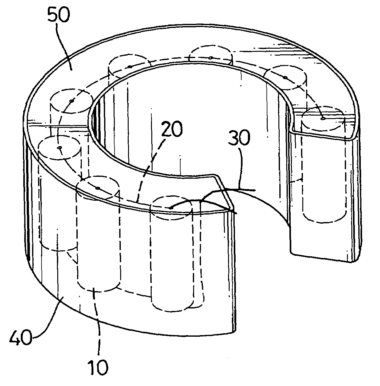
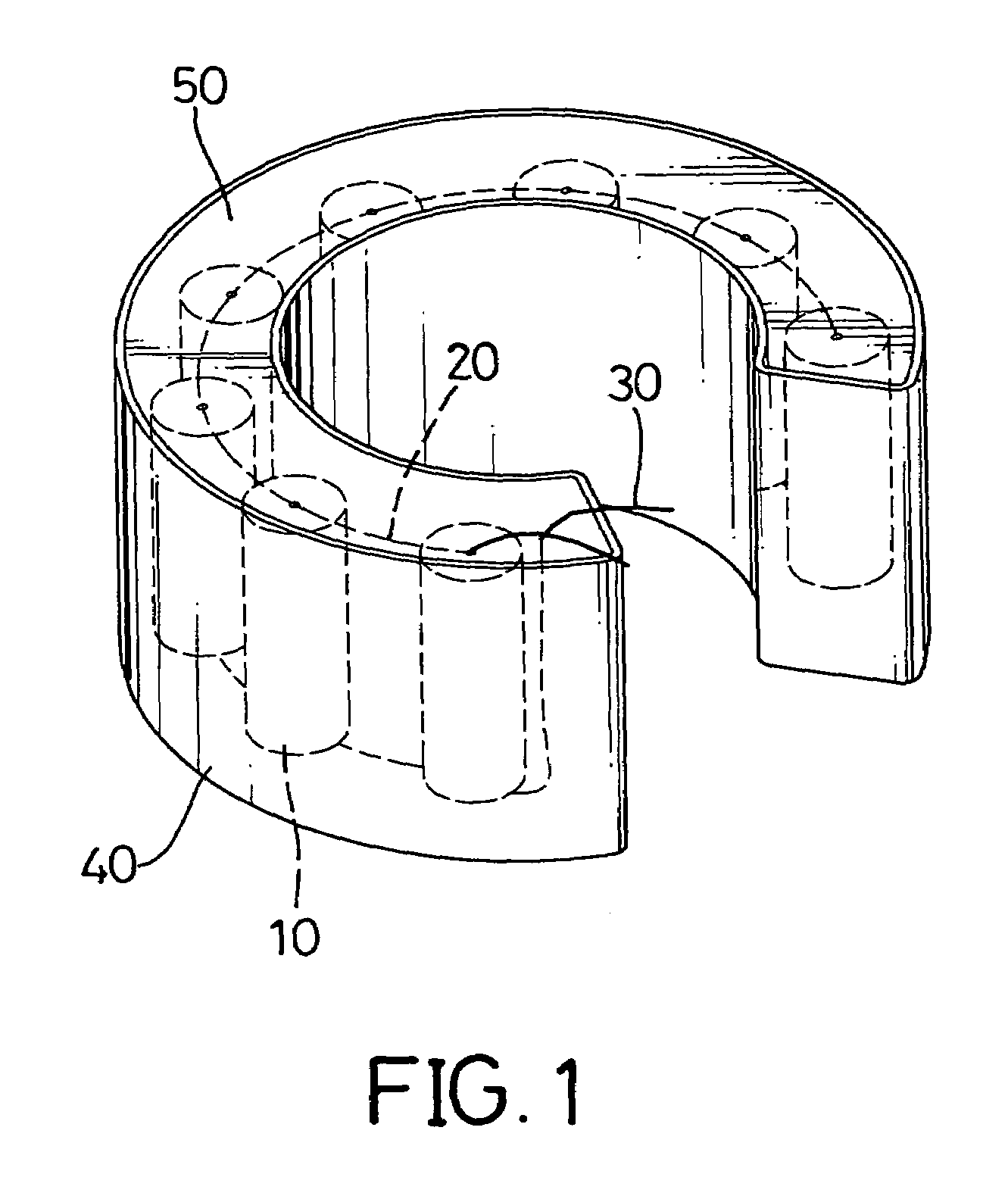
[0016]With reference to FIG. 1, a C-shaped combination capacitor assembly in accordance with the present invention comprises a C-shaped shell (40), multiple capacitors (10), two conducting wires (20), two lead wires (30) and encapsulant (50).

[0017]The C-shaped shell (40) is hollow and has an inner space and a top 8 opening.

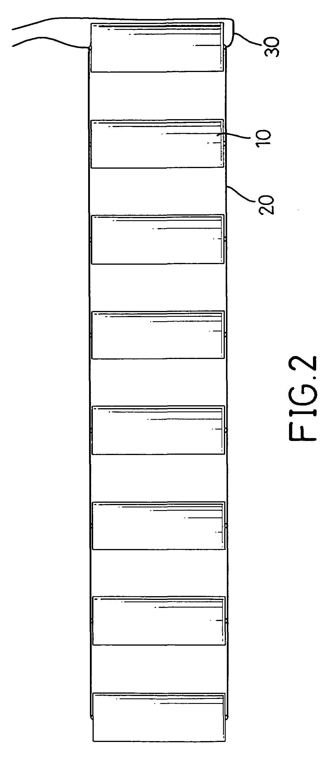
[0018]With further reference to FIGS. 2 and 3, the capacitors (10) are mounted in the inner space of the C-shaped shell (40), and each capacitor (10) has a positive pole, a negative pole and a capacitance. One of the two conducting wires (20) connects to the positive poles of the capacitors (10), and the other conducting wire (20) connects to the negative poles of the capacitors (10) to connect the capacitors (10) in parallel. According to the formula to calculate the capacitance of capacitors connected in parallel: Csum=C1+C2+C3+ . . . +Cn, connecting the capacitors (10) in parallel results in a capacitance equal to the sum of the capacitance of the individual ca...


PUM


Abstract

A C-shaped combination capacitor assembly has a C-shaped shell, multiple capacitors, two conducting wires, two lead wires and encapsulant. The capacitors are mounted in the C-shaped shell. The conducting wires connect the capacitors in parallel. The two lead wires connect respectively to the conducting wires and protrude from the C-shaped shell. The encapsulant fills the C-shaped shell and covers and seals the capacitors, the conducting wires and the lead wires inside the C-shaped shell.

Description

BACKGROUND OF THE INVENTION[0001]1. Field of the Invention[0002]The present invention relates to a C-shaped capacitor assembly, especially to a C-shaped combination capacitor assembly for a submersible motor.[0003]2. Description of the Prior Arts[0004]A water pump needs a motor to provide power. When the motor is working, the motor usually makes a loud noise. Therefore submersible motors are used widely with water pumps to reduce the loud noise. With reference to FIG. 5, a conventional submersible motor (60) comprises an outer shell (62), an additional shell (61) and a capacitor (70). The additional shell (61) is mounted on and communicates with one end of the outer shell (62). The capacitor (70) is mounted in the additional shell (61). The additional shell (61) with the capacitor (70) increases the volume of the conventional submersible motor (60). Furthermore, water easily enters the joint between the outer shell (62) and the additional shell (61), which causes the conventional su...

Claims


Application Information

Patent Timeline
IPC IPC(8): H01G4/005
CPCH01G9/14H01G9/08
Inventor HUANG, SHOU-HSIUNG
Owner HUANG SHOU HSIUNG
Why Eureka
Try Eureka