Data center cooling

a data center and cooling technology, applied in the direction of domestic cooling apparatus, lighting and heating apparatus, and semiconductor/solid-state device details, etc., can solve problems such as power supply interruption

Inactive Publication Date: 2006-05-16
SCHNEIDER ELECTRIC IT CORP
View PDF2 Cites 221 Cited by
  • Summary
  • Abstract
  • Description
  • Claims
  • Application Information

AI Technical Summary

Benefits of technology

[0025]Implementations of the invention may include one or more of the following features. The cooling means is configured to direct the relatively cool gas toward bottom portions of the fronts of the first portion of the housings. The cooling means is configured to cool the heated gas to approximately 72° F. to produce the relatively cool gas. The closure means includes at least one thermally-insulated door configured to be opened to provide access to the hot region and closed to inhibit the heated gas from laterally exiting the hot region between the housings to which the closure means is coupled. The housings are disposed in two parallel rows, and wherein the closure means includes two doors disposed at opposite ends of the rows and coupling the two rows to each other at the respective ends. The system further includes an uninterruptible power supply coupled to the cooling means and configured to provide backup power to the cooling means.
[0026]In general, in another aspect, the invention provides a method of operating and cooling rack-mounted electronic equipment, the method including powering the rack-mounted electronic equipment to draw gas into housings containing the equipment through fronts of the housings, heat the gas to produce heated gas, and expel the heated gas into a hot region, inhibiting the heated gas from laterally exiting the hot region, except into a cooling mechanism, using the housings containing the equipment and at least one panel coupled to at least two of the housings while allowing the heated gas to upwardly exit the hot region substantially unimpeded at least until the gas rises above tops of the housings, drawing in at least some of the heated gas from the hot region into the cooling mechanism and cooling the drawn-in gas to produce cool gas, and providing the cool gas to fronts of the housings.
[0027]Implementations of the invention may include one or more of the following features. The inhibiting includes injecting more heated gas into the hot region and impeding lateral flow of the heated gas with at least one barrier coupled between a gap between a pair of the housings. The providing includes directing the cool gas toward bottoms of the fronts of the housings.

Problems solved by technology

Additionally, the method can include using an uninterruptible power supply to provide power to equipment in the racks.

Method used


Image

  • Data center cooling
  • Data center cooling
  • Data center cooling

Examples


Embodiment Construction

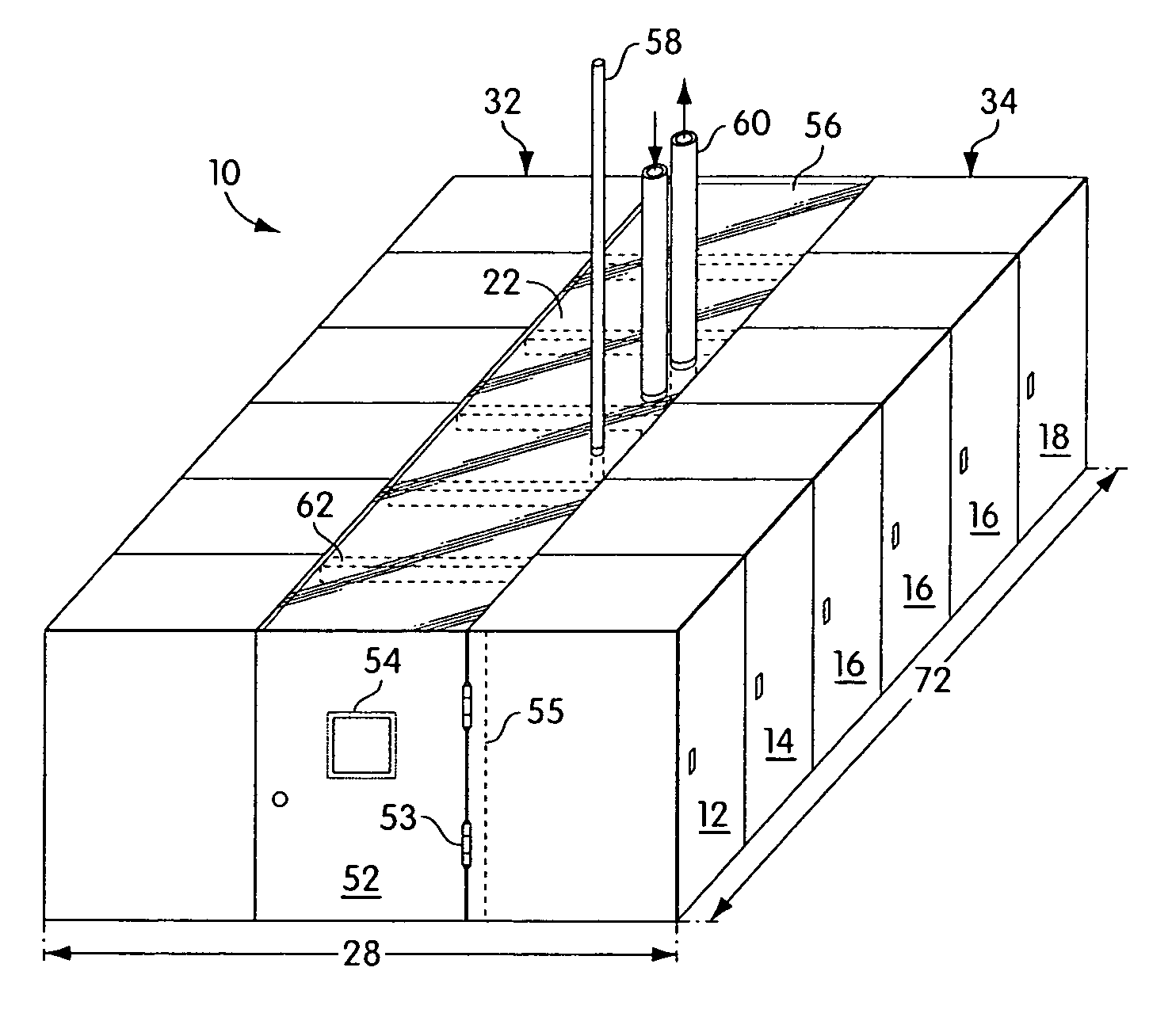
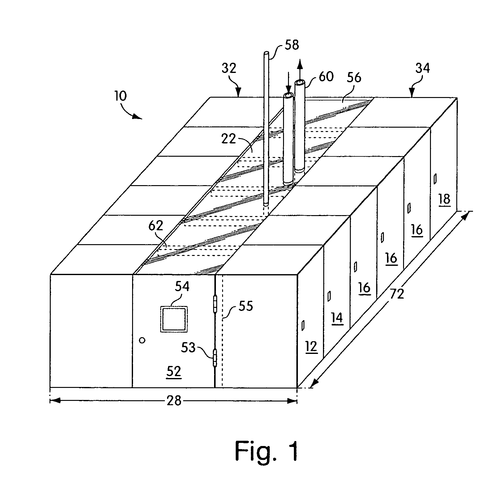
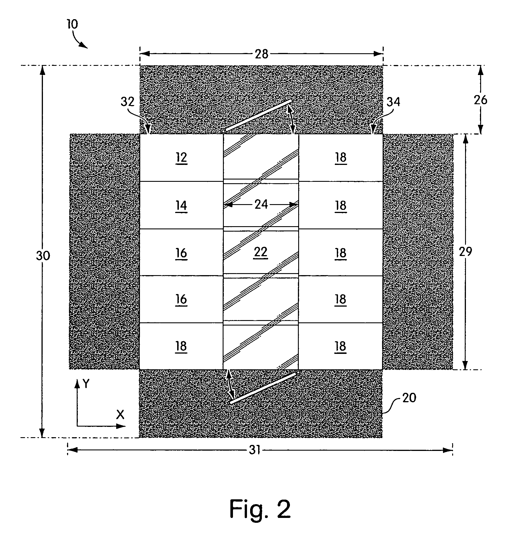
[0035]Embodiments of the invention provide a data center infrastructure having a cooling system for cooling rack-mounted electronic equipment. Embodiments of the invention provide a modular data center for rack-mounted equipment, wherein the modular data center provides power distribution, cooling and structural support for the rack-mounted equipment. The power distribution unit and cooling is provided in some embodiments using redundant systems to prevent downtime due to electrical or mechanical failures. As understood by those skilled in the art, other embodiments are within the scope of the invention, such as embodiments used to provide infrastructure for equipment other than electronic equipment.

[0036]A system for providing power distribution for rack-mounted equipment, which can be used with embodiments of the present invention, is described in U.S. patent application Ser. No. 10 / 038,106, entitled, “Adjustable Scalable Rack Power System and Method,” which is herein incorporated...


PUM


Abstract

A modular data center, for housing and cooling electronic equipment, includes multiple housings, a first portion of the housings configured to hold heat-producing electronic equipment and a second portion of the housings configured to hold at least one cooling unit, each of the housings of the first portion having a front and a back and configured to hold the heat-producing electronic equipment such that gas is drawn into the equipment from fronts of the equipment, heated by the equipment to become heated gas, and expelled by the electronic equipment is expelled through the backs of the housings, and at least one panel coupled to a pair of the housings to bridge a gap between the pair of the housings, where the housings and the at least one panel are disposed and coupled to form a laterally-enclosed arrangement laterally enclosing a hot region and defining a top opening allowing gas to vertically exit the hot region, and where backs of the housings of the first portion are disposed adjacent to the hot region such that the heat-producing equipment, when mounted to the housings, will expel the heated gas into the hot region.

Description

CROSS-REFERENCE TO RELATED ACTIONS[0001]This application is a continuation-in-part, and claims the benefit, of U.S. application Ser. No. 10 / 391,971 filed Mar. 19, 2003 now U.S. Pat. No. 6,859,366.FIELD OF THE INVENTION[0002]Embodiments of the present invention are directed to cooling of rack-mounted devices, and more particularly to a data center infrastructure having a cooling system.BACKGROUND OF THE INVENTION[0003]Communications and information technology equipment is commonly designed for mounting to racks and for housing within enclosures. Equipment racks and enclosures are used to contain and to arrange communications and information technology equipment, such as servers, CPUs, internetworking equipment and storage devices, in small wiring closets as well as equipment rooms and large data centers. An equipment rack can be an open configuration and can be housed within a rack enclosure. A standard rack typically includes front-mounting rails to which multiple units of equipment...

Claims


Application Information

Patent Timeline
Patent Type & Authority Patents(United States)
IPC IPC(8): H05K7/20F24F11/75F24F11/76H05K7/00
CPCH05K7/20H05K7/2079H05K7/20745
Inventor FINK, JAMES R.BEAN, JR., JOHN H.HELD, STEPHEN F.JOHNSON, RICHARD J.JOHNSON, ROLLIE R.
Owner SCHNEIDER ELECTRIC IT CORP
Why Eureka
Try Eureka