Light guide pillar

a light guide and pillar technology, applied in the field of light guide pillars, can solve the problems of color mixing, inconvenient use, and difficulty for users to clearly identify the message of the indicator

Inactive Publication Date: 2006-05-16
INVENTEC CORP
View PDF12 Cites 17 Cited by
  • Summary
  • Abstract
  • Description
  • Claims
  • Application Information

AI Technical Summary

Benefits of technology

[0007]It is an object of the present invention to provide a light guide pillar. The light guide pillar is disposed on a circuit board of an electronic apparatus. The circuit board comprises a light emitting element disposed thereon. The light guide pillar includes a bulk and a pillar. The bulk is opaque and is disposed on the circuit board. The bulk covers the light emitting element disposed on the circuit board. One end of the pillar is inserted into the bulk, while the other end of the pillar is extended outside of the electronic apparatus. The light source generated from the light emitting element is thus guided and displayed outside of the electronic apparatus via the light guide pillar. In this manner, the bulk can stop the light source emitted from the light emitting element from dispersing. Therefore, the light source can be guided to outside of the electronic apparatus without interference.

Problems solved by technology

However, regardless of whether the light guide pillars emit light in a single direction or in a multiple of directions, the user will experience inhomogeneous or leaking luminescence when looking at the light guide pillar, which renders the usage very inconvenient.
Since the separation between the LEDs is very close to each other, the emitted light often interferes with each other, resulting in color mixing.
For this reason, it is difficult for users to clearly identify the message that the indicator is displaying when the indicator is displaying two or more colors at the same time.
However, this solution requires the compliance of the circuit board and the appearance.
Moreover, such light intervention still remains when the luminescence of the LEDs is too high.
Therefore, the problems of the conventional light guide pillars are not yet solved.

Method used


Image

  • Light guide pillar
  • Light guide pillar
  • Light guide pillar

Examples


Embodiment Construction

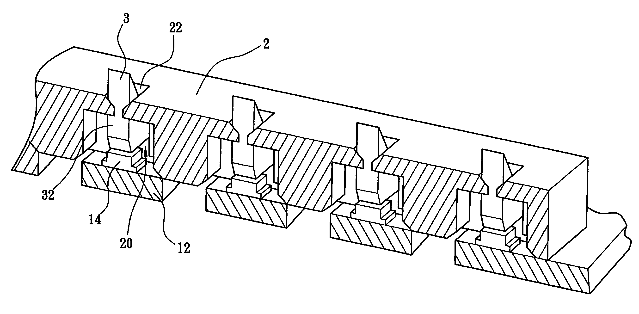
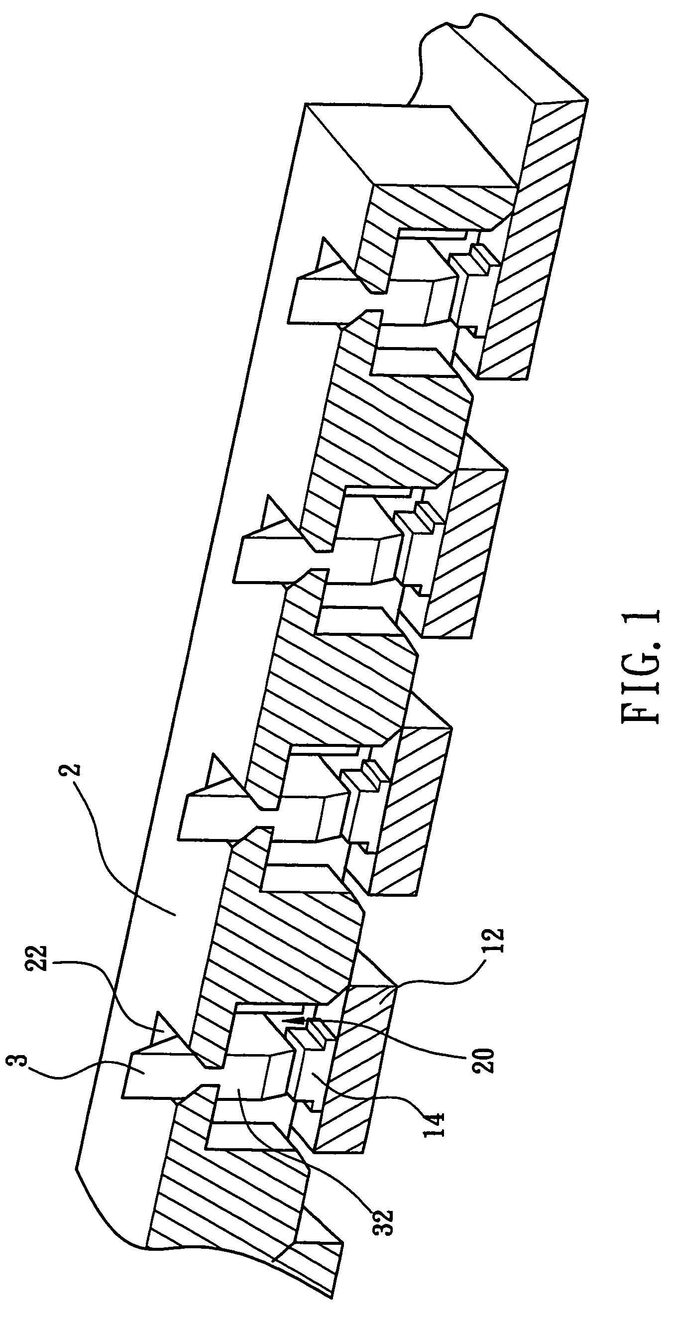
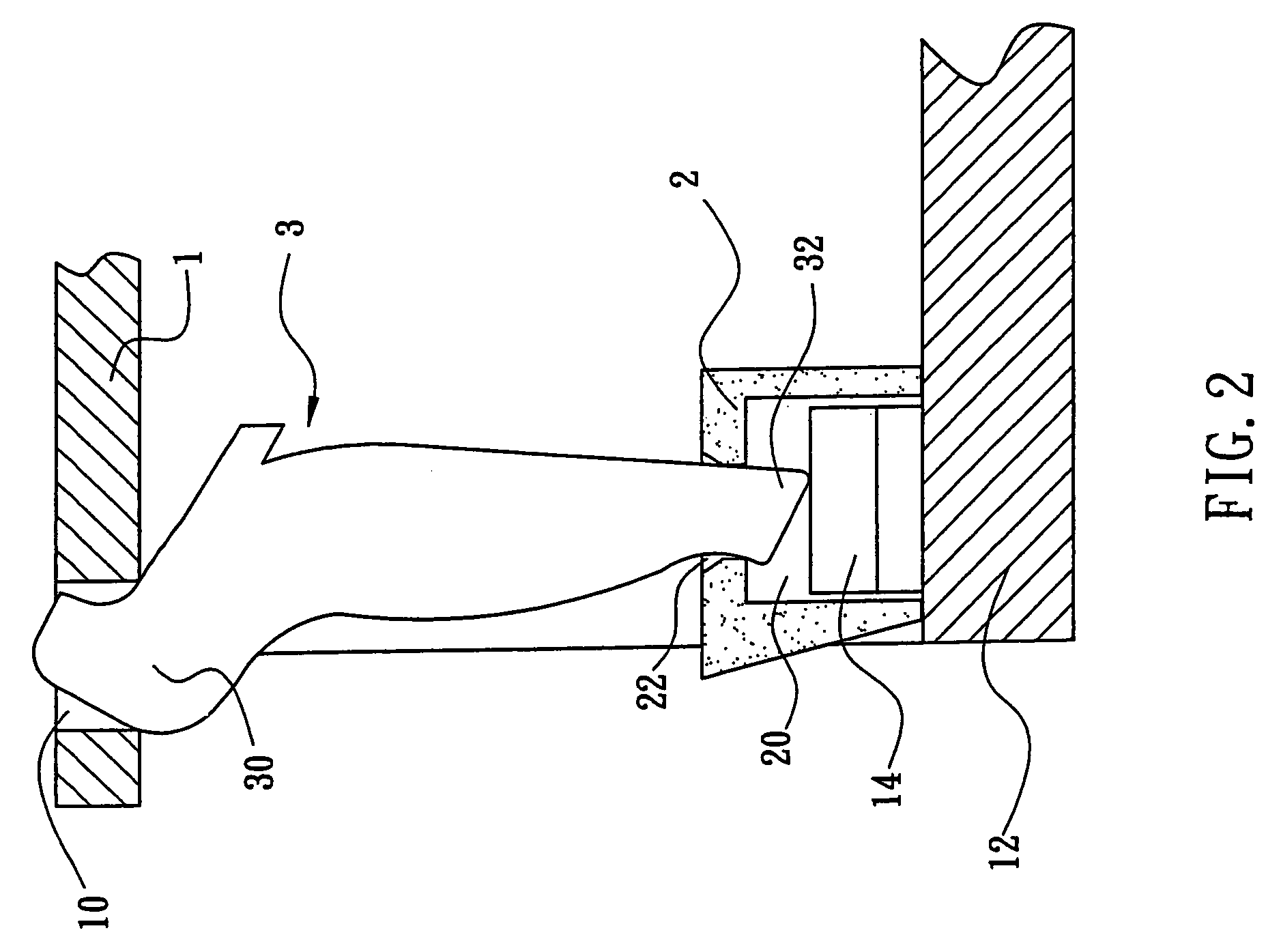
[0011]Referring to FIG. 1 and FIG. 2, the light guide pillar of the present invention being installed on a circuit board 12 of an electronic apparatus are illustrated. The circuit board 12 comprises a light emitting element 14. The light emitted from the light emitting element 14 is directed outside of the electronic apparatus via the light guide pillar. The light guide pillar comprises an opaque bulk 2, which is disposed on the circuit board 12 of the electronic apparatus. The light emitting element 14 is just covered by the bulk 2. A pillar 3 is deposed on the bulk 2. One end of the pillar 3 is inserted in the bulk 2, while the other end of the pillar 3 is extended outside the housing 1 of the electronic apparatus. In this way, the bulk 2 can stop the light source emitted from the light emitting element 14 from dispersing. The light source is further guided outside of the housing 1. The light guide pillar of the present invention can easily prevent light source from dispersing and...


PUM


Abstract

The present invention is to provide a light guide pillar disposed on a circuit board of an electronic apparatus having a light emitting element disposed thereon, where the light guide pillar includes a bulk opaque and disposed on the circuit board for covering the light emitting element and a pillar with one end inserted into the bulk while the other end thereof extended outside of the electronic apparatus, enabling the light source generated from the light emitting element to be guided and displayed outside of the electronic apparatus via the light guide pillar and enabling the bulk to stop the light source emitted from the light emitting element from dispersing. Therefore, the light source can be guided to outside of the electronic apparatus without interference.

Description

FIELD OF THE INVENTION[0001]The present invention relates to a light guide pillar, more particularly to a light guide pillar being disposed in an electronic apparatus for stopping the light source emitted from the light emitting element from dispersing and guiding the light source to outside of the electronic apparatus without interference.BACKGROUND OF THE INVENTION[0002]A light emitting diode (LED) is normally a light emitting PN junction diode composed of III-V or II-VI semiconductor compounds, such as GaAs, GaP, AlxGa1-xAs, ZnSe, etc. When a forward bias is applied to the LED, the electrons in the N-type semiconductor combines with the holes in the P-type semiconductor. Since the electrons transition to a lower energy level, the superfluous energy is converted to photons, thereby emitting light. Since the electrons and the holes are continuously provided to the N-type and the P-type semiconductors from the current of the power source, the light emission process due to the electr...

Claims


Application Information

Patent Timeline
Patent Type & Authority Patents(United States)
IPC IPC(8): G02B6/10
CPCG02B6/0036G02B6/0013
Inventor CHO, YU-CHI
Owner INVENTEC CORP
Why Eureka
Try Eureka