Compensation method of resolver detected position

a technology of resolution method and detection position, applied in the field of compensation method of resolution position, to achieve the effect of improving position detection precision

Active Publication Date: 2006-05-16
SANYO DENKI CO LTD
View PDF8 Cites 23 Cited by
  • Summary
  • Abstract
  • Description
  • Claims
  • Application Information

AI Technical Summary

Benefits of technology

[0009]The present invention aims at an improvement on a resolver detected position compensation method which performs a static error compensation on a resolver detected position by compensating a static error defined as an error from a real position of a rotor of the resolver that occurs when the rotor is at rest. This invention further performs a dynamic error compensation on the compensated detected position obtained by the static error compensation to eliminate a dynamic error defined as an error from a real position of the rotor that occurs when the rotor is rotating. The dynamic error means an error which, despite the static error compensation, occurs and varies as the rotor rotates. Performing the dynamic error compensation on the compensated detected position obtained by the static error compensation, as proposed in this invention, can eliminate the dynamic error that varies as the rotational speed of the rotor changes. This in turn enhances a resolver position detection accuracy. Particularly, according to this invention, even when the speed of the rotor of the resolver becomes high, the resolver position detection accuracy can be enhanced.
[0010]More specifically, whether the rotor is running at low speed or at high speed (e.g., more than 10,000 min−1), the dynamic error includes twice as many ripples that appear during one rotation of the rotor as the number of pole pairs. So, performing a dynamic error compensation, which removes from the compensated detected position signal obtained by the static error compensation a dynamic error signal that contains twice as many ripples that appear during one rotation of the rotor as the number of pole pairs of the resolver, can reliably eliminate the dynamic error from the compensated detected position signal.
[0011]Any desired method of dynamic error compensation may be employed. For instance, the dynamic error compensation may be executed as follows. First, a phase of a dynamic error signal that varies according to the rotational position of the rotor is measured in advance at various rotational speeds of the rotor. Further, an amplitude peak value of the dynamic error signal that varies with a speed of the rotor is measured beforehand at various rotational speeds of the rotor. Then, for a particular rotor speed, the corresponding variation in phase and amplitude peak value of the dynamic error signal are multiplied to determine an estimated dynamic error. This estimated dynamic error is subtracted from the compensated detected position signal. With this method, the estimated dynamic error can be determined easily based on the variation in phase and amplitude peak value of the dynamic error signal, both measured beforehand at various speeds of the rotor. Simply subtracting the estimated dynamic error from the compensated detected position signal completes the dynamic error compensation. The entire process of the dynamic error compensation thus can be performed easily and reliably.
[0013]The dynamic error compensation circuit may be constructed to remove from the compensated detected position signal a dynamic error which includes twice as many ripples that appear during one rotation of the rotor as the number of pair poles of the resolver. More specifically, the dynamic error compensation circuit comprises: a phase data memory means to store dynamic error phase data which is obtained by measuring beforehand a variation in phase of the dynamic error signal that varies according to the rotational position of the rotor at various rotational speeds of the rotor; a peak value memory means to store dynamic error amplitude peak value data which is obtained by measuring beforehand an amplitude peak value of the dynamic error signal that varies with the rotational speed of the rotor at various rotational speeds of the rotor; a differential circuit to determine the rotational speed by differentiating an output of the position detection circuit; a multiplication means to multiply the variation in phase and the amplitude peak value, read from the phase data memory means and the peak value memory means respectively according to an output of the differential circuit, to determine an estimated dynamic error; and a subtraction circuit to subtract the estimated dynamic error from the compensated detected position signal. With this configuration the dynamic error compensation circuit can easily be formed.
[0014]As described above, by further performing a dynamic error compensation on the compensated detected position obtained by the static error compensation, the error that varies with a changing speed of the rotor can be compensated, improving the position detection precision over those of the conventional resolvers.

Problems solved by technology

The dynamic error means an error which, despite the static error compensation, occurs and varies as the rotor rotates.

Method used


Image

  • Compensation method of resolver detected position
  • Compensation method of resolver detected position
  • Compensation method of resolver detected position

Examples


Embodiment Construction

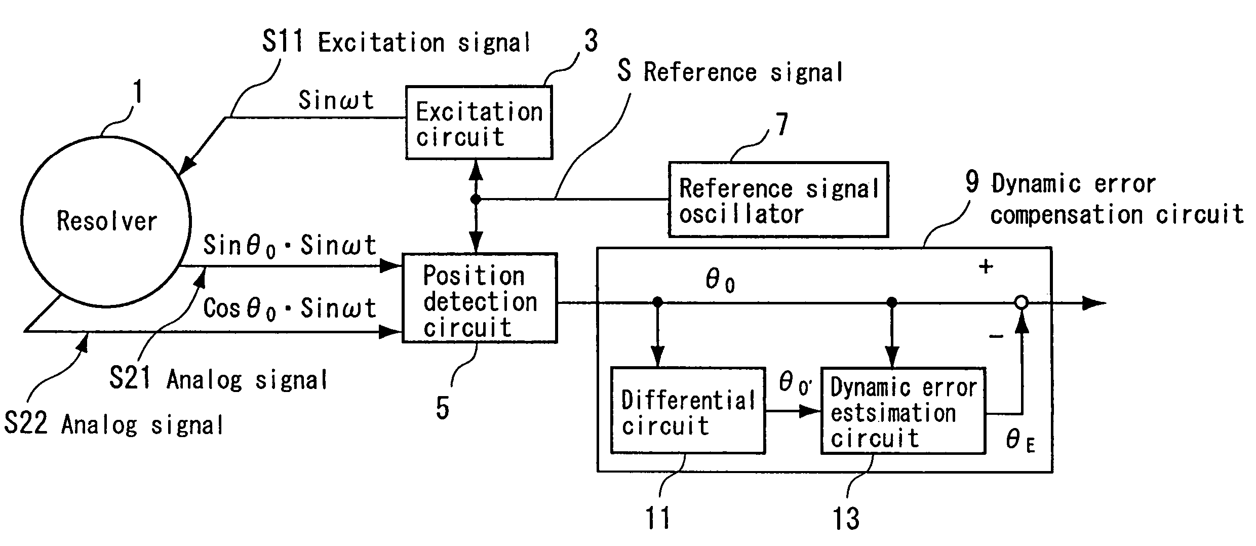
[0020]Now one embodiment of this invention will be described by referring to the accompanying drawings. FIG. 1 is a block diagram showing an example construction of a resolver detected position compensation system for a resolver, which embodies the resolver detected position compensation method of this invention.

[0021]In FIG. 1, a resolver designated at reference numeral 1 has a rotor and excitation windings both not shown. The resolver 1 is mounted on a rotary shaft of a rotating apparatus such as motor, not shown, and outputs analog signals representing a rotational position of the rotary shaft of the rotating apparatus. To remove not only a static error but also a dynamic error from the detection signal representing the rotor position which is output from the resolver 1, this system has an excitation circuit 3, a position detection circuit 5, a reference signal oscillator 7 to supply a reference signal S to the excitation circuit 3 and the position detection circuit 5, and a dyna...


PUM


Abstract

A resolver detected position compensation system for a resolver is provided that can enhance a position detection precision by performing a further compensation on a compensated position that was obtained from a static error compensation. The position detection circuit outputs a compensated detected position signal in which a static error has been compensated. The differential circuit differentiates the compensated detected position signal to obtain a rotational speed of the resolver. Based on a signal representing the rotational speed output from the differential circuit, the phase data memory device and the peak value memory device send the variation in phase and the amplitude peak value, respectively, of the dynamic error signal to the multiplication device. The multiplication device calculates an estimated dynamic error and the subtraction circuit removes the estimated dynamic error from the compensated detected position signal.

Description

BACKGROUND OF THE INVENTION[0001]The present invention relates to a method and a system for compensating a detected position detected by a resolver.[0002]Japanese Patent No. 2541169 and Japanese Patent Laid-open Publication No. 7-336979 show conventional techniques for compensating a position detected by a resolver. These prior arts compensate the detected position by performing a static error compensation by which a static error defined as an error from a real position when a rotor of the resolver is at rest, is compensated.[0003]With the conventional technique of Japanese Patent No. 2541169 in particular, as claimed in its claims, the position compensation procedure involves differentiating a detected position signal from the resolver when a motor is driven at a constant speed, calculating from the differentiated signal position compensation data corresponding to rotational positions of the rotor, and storing the calculated result in memory. When a motor is controlled, the positio...

Claims


Application Information

Patent Timeline
Patent Type & Authority Patents(United States)
IPC IPC(8): G01C17/38G01R31/34G01D5/244G01D5/245G01R31/00
CPCG01D5/24476
Inventor ISHIZUKA, YOSHIMAKIUCHI, KAZUHIROMIYAJIMA, TORU
Owner SANYO DENKI CO LTD
Why Eureka
Try Eureka