Method of generating a grid on a heterogenous formation crossed by one or more geometric discontinuities in order to carry out simulations

Inactive Publication Date: 2006-05-16
INST FR DU PETROLE
View PDF5 Cites 88 Cited by
  • Summary
  • Abstract
  • Description
  • Claims
  • Application Information

AI Technical Summary

Benefits of technology

[0041]Using a reservoir simulator of a well-known type, such as ATHOS™ or SCORE™ for example, for a reservoi

Problems solved by technology

However, the gridding techniques used in the other fields cannot be applied to petroleum applications because the professional constraints are not the same.
The saturation, constant in the control volume, could not consider discontinuities and the results would not be accurate.
Cartesian grids, which are commonly used in current commercial simulators, are unsuited for solving these new problems posed by the development of petroleum reservoirs.
Cartesian grids, based on parallelepipedic elements, do not allow representation of such complex geometries.
However, this type of grid does not allow solution of all geometric complexities such as, for example, circular radial grids around complex wells.
It is possible to form separately the grid of the reservoir and the grids around the wells but it is difficult to represent several objects in the same CPG type reservoir grid because of connection problems linked with the structured nature of the grid.
However, this method has drawbacks which make the results obtained difficult to use:
there are on average five times as many grid cells as in a CPG type grid for the same structure, which is very disadvantageous for simulation calculations,
unlike the structured grids which are easy to display, to explore

Method used


Image

  • Method of generating a grid on a heterogenous formation crossed by one or more geometric discontinuities in order to carry out simulations
  • Method of generating a grid on a heterogenous formation crossed by one or more geometric discontinuities in order to carry out simulations
  • Method of generating a grid on a heterogenous formation crossed by one or more geometric discontinuities in order to carry out simulations

Examples


Embodiment Construction

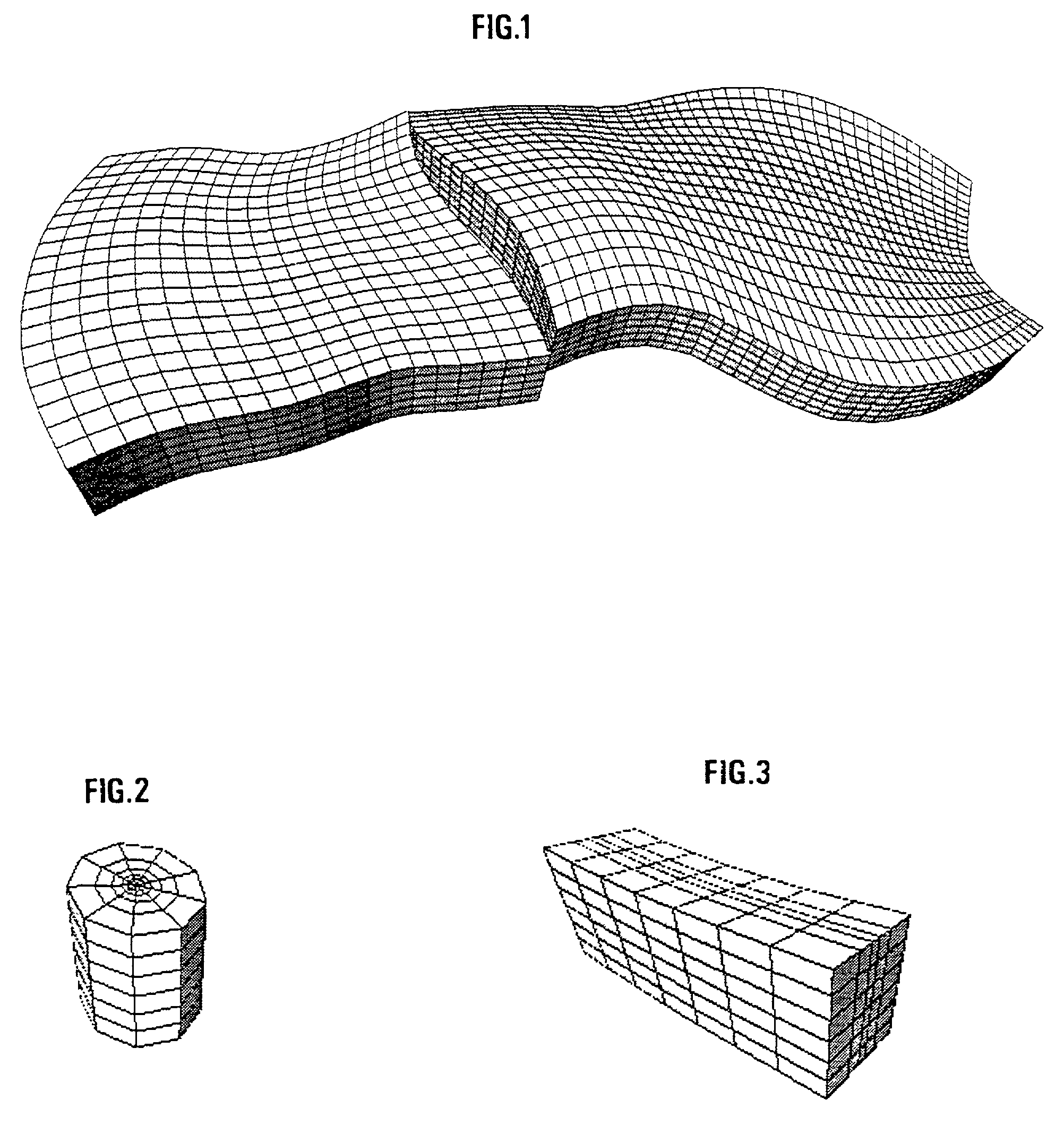
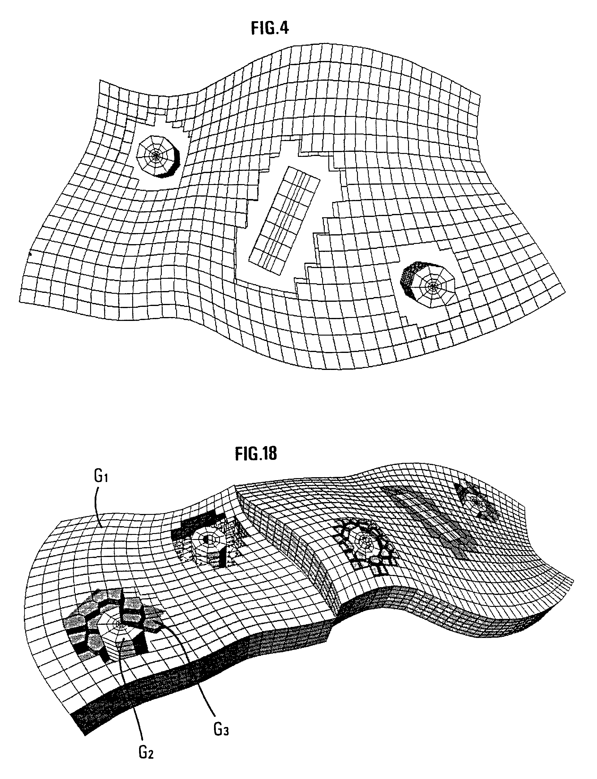
[0056]Generation of the hybrid reservoir grid is carried out in stages with addition / subtraction of elementary grids of different types.

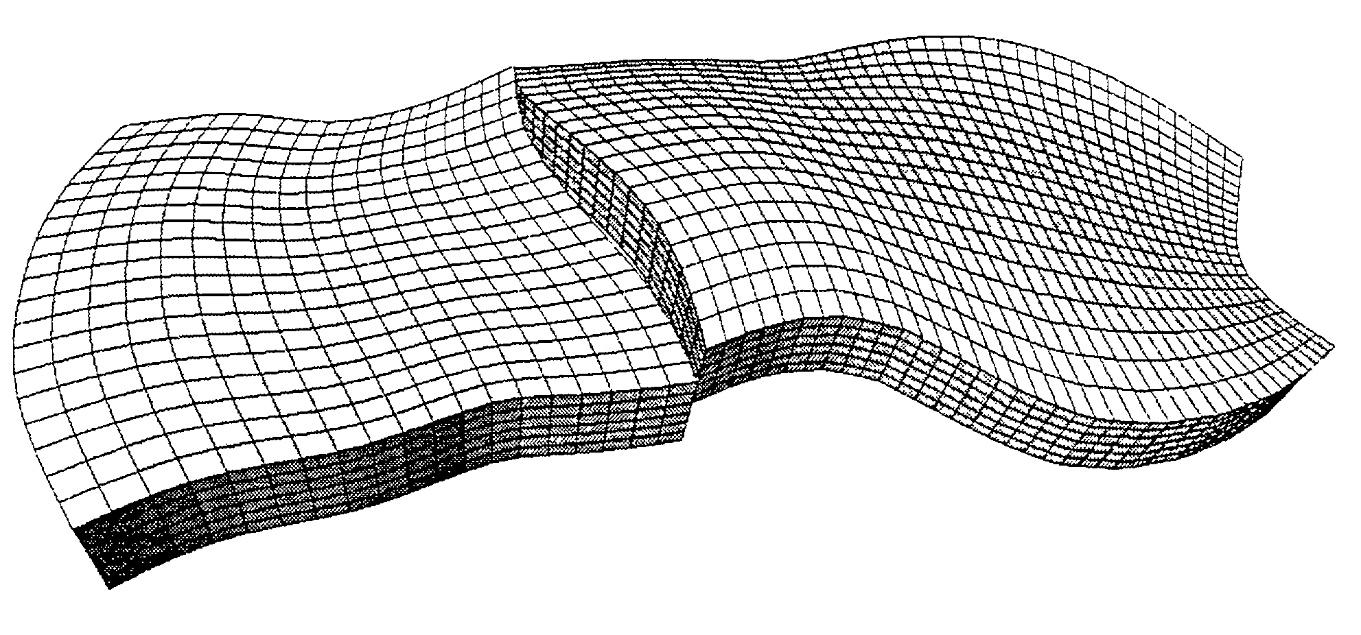
[0057]1) In order to represent the reservoir as a whole, an i, j, k structured grid of a known type, referred to as CPG, as described in the aforementioned French patent 2,747,490 filed by the assignee, is for example used.

[0058]The reservoir can be faulted with downcreep of a block in relation to the other. The major horizons and faults are first modelled by continuous surfaces from data resulting from an interpretation of seismic images of the subsoil or from data obtained during drilling (well markers). The geologic structure is then divided into faulted blocks resting on these surfaces. These blocks are individually gridded and then reassembled. Gridding of a block first consists in gridding the edge surfaces, then the inside is populated by transfmite interpolation of the edge surface grids. Relaxation techniques are then applied to the edge su...


PUM


Abstract

A method of generating a hybrid grid of a heterogeneous formation crossed by one or more geometric discontinuities such as, for example, an underground formation where one or more wells have been drilled, or a fractured formation, by combining structured grids and non-structured grids in order to carry out simulations in accordance with a defined numerical pattern is disclosed. Hybrid gridding is performed by associating a first structured grid (G1) for gridding of the heterogeneous medium considering discontinuities thereof with second structured, radial type grids (G2) for gridding of a zone around each pipe or well, which allows better consideration of constraints linked with flows in the zone. In order to connect the first grid of the medium and the second well grids, non-structured transition grids (G3) are interposed there between. A power diagram technique is used, which is particularly advantageous in that it allows appropriate connection of non-regular structured grids. An application is hydrocarbon reservoir simulation.

Description

BACKGROUND OF THE INVENTION[0001]1. Field of the Invention[0002]The present invention relates to a method of generating a hybrid grid of a heterogeneous formation crossed by one or more geometric discontinuities in order for example to carry out simulations.[0003]The method is more particularly applied to formation of a grid suited to an underground reservoir crossed by one or more wells, or by fractures or faults, in order to model displacements of fluids such as hydrocarbons.[0004]2. Description of the Prior Art[0005]Grid generation is a crucial element for the new generation of reservoir simulators. Grids allow to describe the geometry of the geologic structure studied by means of a representation in discrete elements wherein simulation is performed according to a suitable numerical pattern. Better comprehension of physical phenomena requires 3D simulation of the multiphase flows in increasingly complex geologic structures, in the vicinity of several types of singularities such a...

Claims


Application Information

Patent Timeline
IPC IPC(8): G06F9/455G06T17/20
CPCG06T17/20G01V99/005
Inventor BALAVEN, SOPHIEBOISSONNAT, JEAN-DANIELBENNIS, CHAKIBSARDA, SYLVAIN
Owner INST FR DU PETROLE
Why Eureka
Try Eureka