Excavator

a technology of excavators and cylinders, applied in the field of excavators, can solve the problems of ineffective upward pushing force at a region, ineffective earth removal operation efficiency, and inapplicability, and achieve the effect of improving the efficiency of the dozer operation

Inactive Publication Date: 2006-05-23
KOBELCO CONSTR MASCH CO LTD
View PDF7 Cites 0 Cited by
  • Summary
  • Abstract
  • Description
  • Claims
  • Application Information

AI Technical Summary

Benefits of technology

[0012]Accordingly, it is an object of the present invention to provide an excavator that is capable of efficiently rolling dirt pushed upward by a dozer unit in the forward direction to inhibit the dirt from falling backward of the dozer unit so as to improve the efficiency of the dozer operation.
[0019]The behavior of dirt during a dozer operation depends on the direction from which the dirt receives force from the blade surface and on the magnitude of the force. In other words, scraped dirt is transferred upward along the blade surface due to the upward pushing force components, but tries to fall downward due to the downward pressing force components. By changing the direction of the upward pushing force components to the forward direction, a release force that tries to roll the dirt forward is generated. When such a release force is sufficiently large, the dirt can be rolled efficiently in the forward direction.
[0023]Accordingly, the dirt at the upper part of the blade surface can be rolled efficiently in the forward direction like a tidal wave so that a pile of dirt that collapses easily in the forward direction and that has a short bottom portion can be formed. Moreover, the dirt can also be pushed quickly and smoothly away towards the opposite lateral sides of the blade. As a result, this achieves a higher efficiency for performing the earth removal operation.

Problems solved by technology

Therefore, according to the related art, the upward pushing force is not effective at a region where the scraped dirt exceeds the height of the blade 12.
This implies that a sufficient release force is not obtained.
This is inefficient for performing an earth removal operation and is not practically appropriate.
In these cases, however, the unique function of the dozer unit 20 of the excavator is not achieved due to the fact that the blade 21 cannot be used as a support for lifting the excavator body when the underside of the excavator is to be, for example inspected or cleaned, or that the blade 21 cannot be used with the excavating attachment unit 9 to hold an object therebetween.
When mini-excavators are to be used to perform a dozer operation at a level lower than the ground level, such a level is limited to about several tens of millimeters since mini-excavators only have small driving power.

Method used


Image

  • Excavator
  • Excavator
  • Excavator

Examples


Embodiment Construction

[0032]An embodiment of an excavator according to the present invention will now be described with reference to FIGS. 1 to 6.

[0033]FIG. 6 illustrates an excavator according to an embodiment of the present invention. Such an excavator is known as a mini-excavator that is equipped with a dozer unit. The excavator includes a crawler-type lower traveling body 1 on which an upper rotatable body 2 is disposed in a rotatable manner about a vertical axis. The upper rotatable body 2 is provided with an excavating attachment unit 9 which includes a boom 3, an arm 4, a bucket 5, and hydraulic cylinders 6, 7, and 8 for respectively driving the boom 3, the arm 4, and the bucket 5.

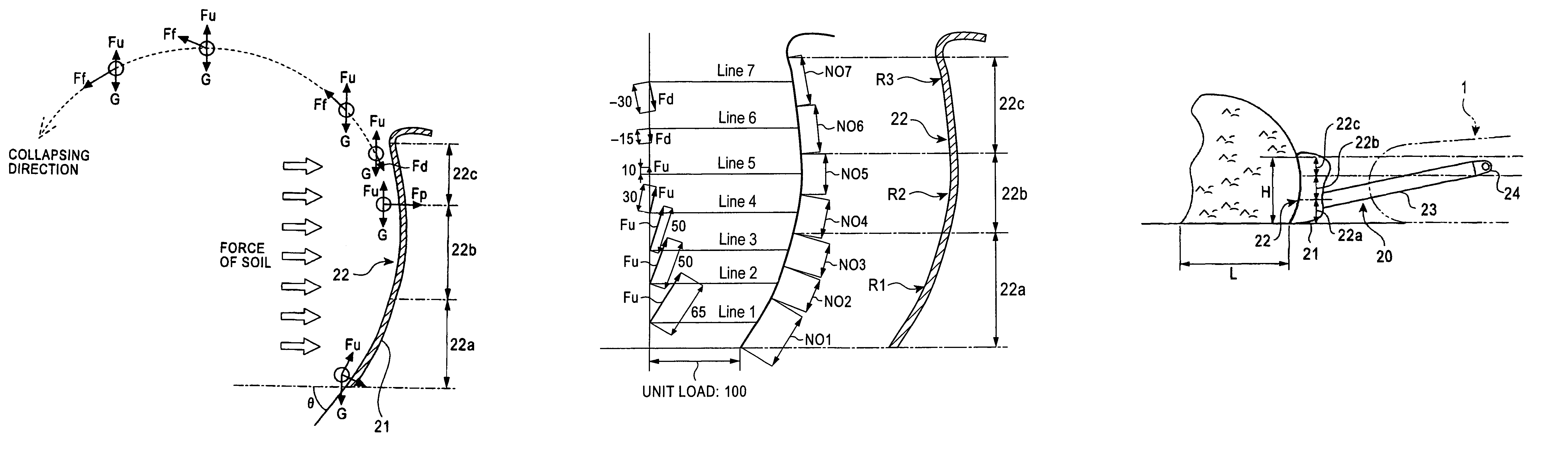
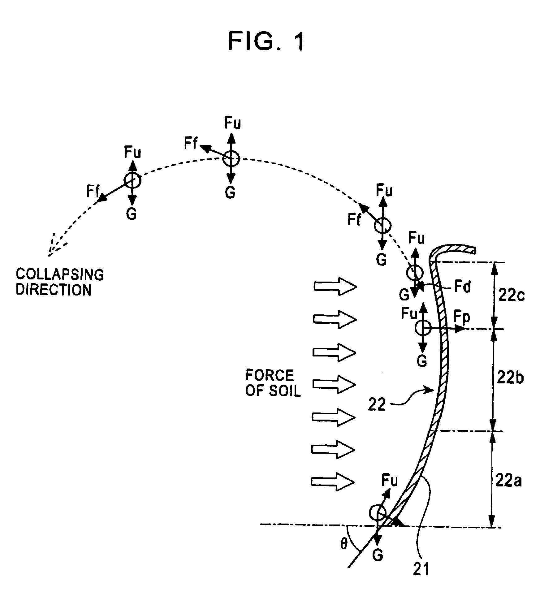
[0034]The excavator further includes a dozer unit 20 provided with a dozer arm 23 and a blade 21. The blade 21 is attached to the front end of the dozer arm 23 in a manner such that the blade 21 is disposed at a predetermined rake angle θ with respect to the ground. On the other hand, the base end of the dozer arm 23 is ...


PUM


Abstract

In an excavator, a blade surface for performing an earth removal operation while a blade is set in contact with the ground satisfies the following conditions: A) upward pushing force components Fu that push dirt upward along the blade surface are generated; B) an upper part of the blade surface has a release surface portion in which a forward-upward release force that rolls the dirt pushed upward by Fu forward is generated; C) when downward pressing force components Fd are generated in response to the generated release force, a total downward pressing force ΣFd> a total upward pushing force ΣFu; and D) if each Fu is given a positive value and if each Fd and a reduced amount of each Fu caused when the dirt hits the release surface portion are given negative values, a value of force at an endmost section of the release surface portion is positive.

Description

BACKGROUND OF THE INVENTION[0001]1. Field of the Invention[0002]The present invention relates to an excavator equipped with a dozer unit for performing an earth removal operation.[0003]2. Description of the Related Art[0004]Referring to FIG. 7, when performing an earth removal operation using a typical excavator equipped with a dozer unit 10 of related art, a blade 12 is projected in a direction indicated by an arrow a in FIG. 7. In this case, however, the dirt accumulated above the blade 12 falls backward over the top surface of the blade 12 in a direction indicated by an arrow b, and thus roughens the finished surface. To prevent this, an additional process is required, such as temporarily raising the blade 12 upward so as to sweep the upper portion of the pile of dirt in the forward direction, or backing up the excavator in order to level the ground over again. As a result, this significantly lowers the efficiency of the earth removal operation.[0005]In order to reduce the amount...

Claims


Application Information

Patent Timeline
Patent Type & Authority Patents(United States)
IPC IPC(8): E02F3/76E01H5/06E02F3/80E02F3/815
CPCE02F3/7609
Inventor OKUNISHI, TAKAYUKISAKITANI, SHINTARO
Owner KOBELCO CONSTR MASCH CO LTD
Why Eureka
Try Eureka