External fixation system

a fixation system and external fixation technology, applied in the field of external fixation system, can solve the problems of inability to properly construct the frame, difficulty in achieving additional reduction, and less adjustment of the fram

Inactive Publication Date: 2006-05-23
SMITH & NEPHEW INC
View PDF142 Cites 133 Cited by
  • Summary
  • Abstract
  • Description
  • Claims
  • Application Information

AI Technical Summary

Benefits of technology

[0008]An external fixation system according to one embodiment of this invention allows manipulation of an external fixation component in any plane independent of the number of fixation components used, which is provided by the ability of the fixation component to rotate in multiple planes. Further, an improved fixation component according to one embodiment of this invention provides an external fixation system that does not bind or become constricted when numerous fixation components are used, providing the surgeon a stable system that is adjustable. One embodiment of a fixation component according to this invention includes two capture members, each adapted to receive a fixation element. The capture members are coupled such that one capture member is capable of rotation in three axes relative to the other capture member and wherein the coupling is adapted to secure the first and second capture members from rotation with a single activation.
[0009]One feature of one embodiment of this invention is a fixation component that provides a greater degree of freedom of rotation.
[0011]Yet another feature is a fixation component that allows one capture member to be locked to retain a fixation element without forcing the second capture member also to be locked, allowing additional adjustment of position of the second capture member.

Problems solved by technology

As additional fixation components are added to the system in different planes, the frame become less adjustable.
Thus, additional reduction is difficult to achieve and requires reestablishment of optional position.
For example, if the pins or wires are angled incorrectly, the frame cannot be properly constructed
This requirement limits the system, as the positioning of each clamp is inhibited.
Similar to other current designs, this design becomes substandard when several fixation components are used because it becomes constrained.
In addition, current designs use compression to hold the bar or pin in place, and may allow dislodgement of the pin or bar upon application of a great amount of pressure to the system when being placed.
These specialized systems do not cooperate with general external fixation systems, and must be used separately.

Method used


Image

  • External fixation system
  • External fixation system
  • External fixation system

Examples


Embodiment Construction

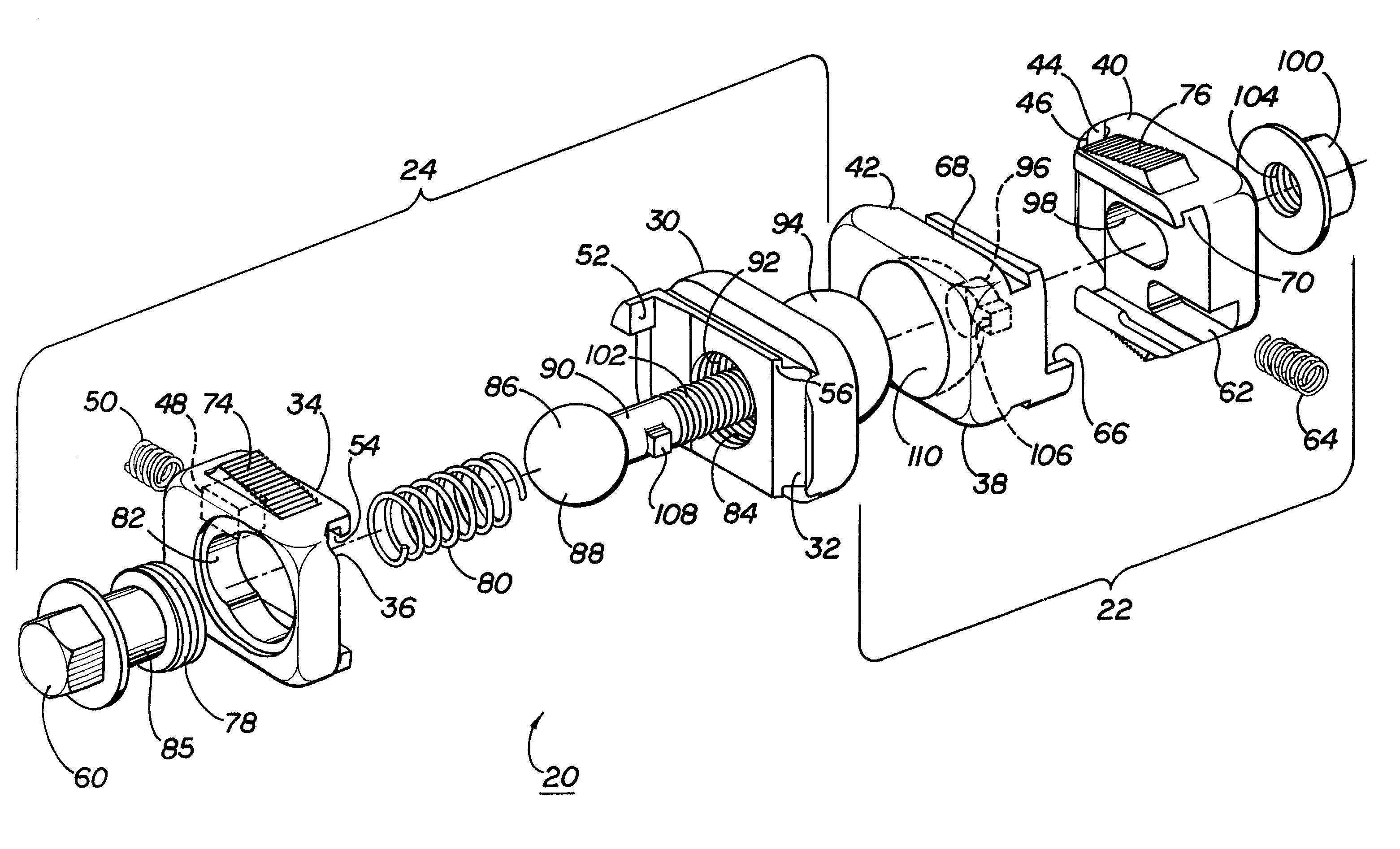
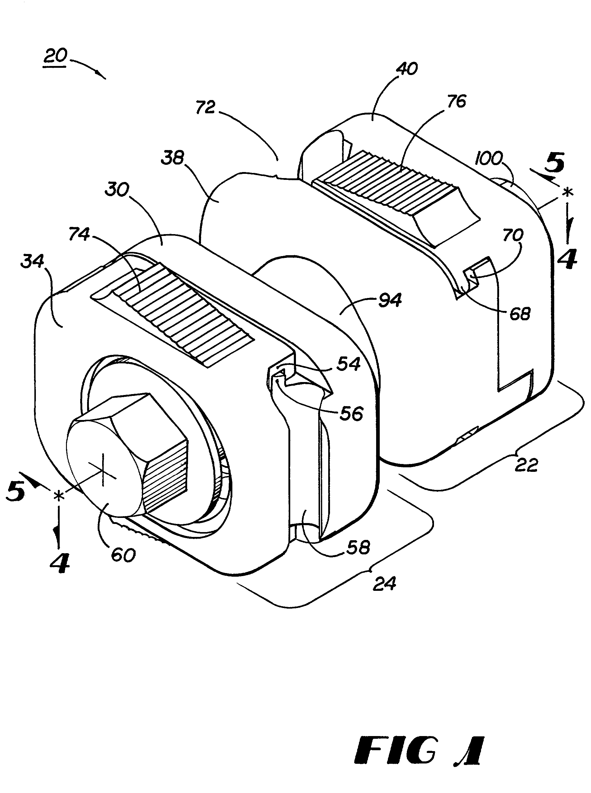
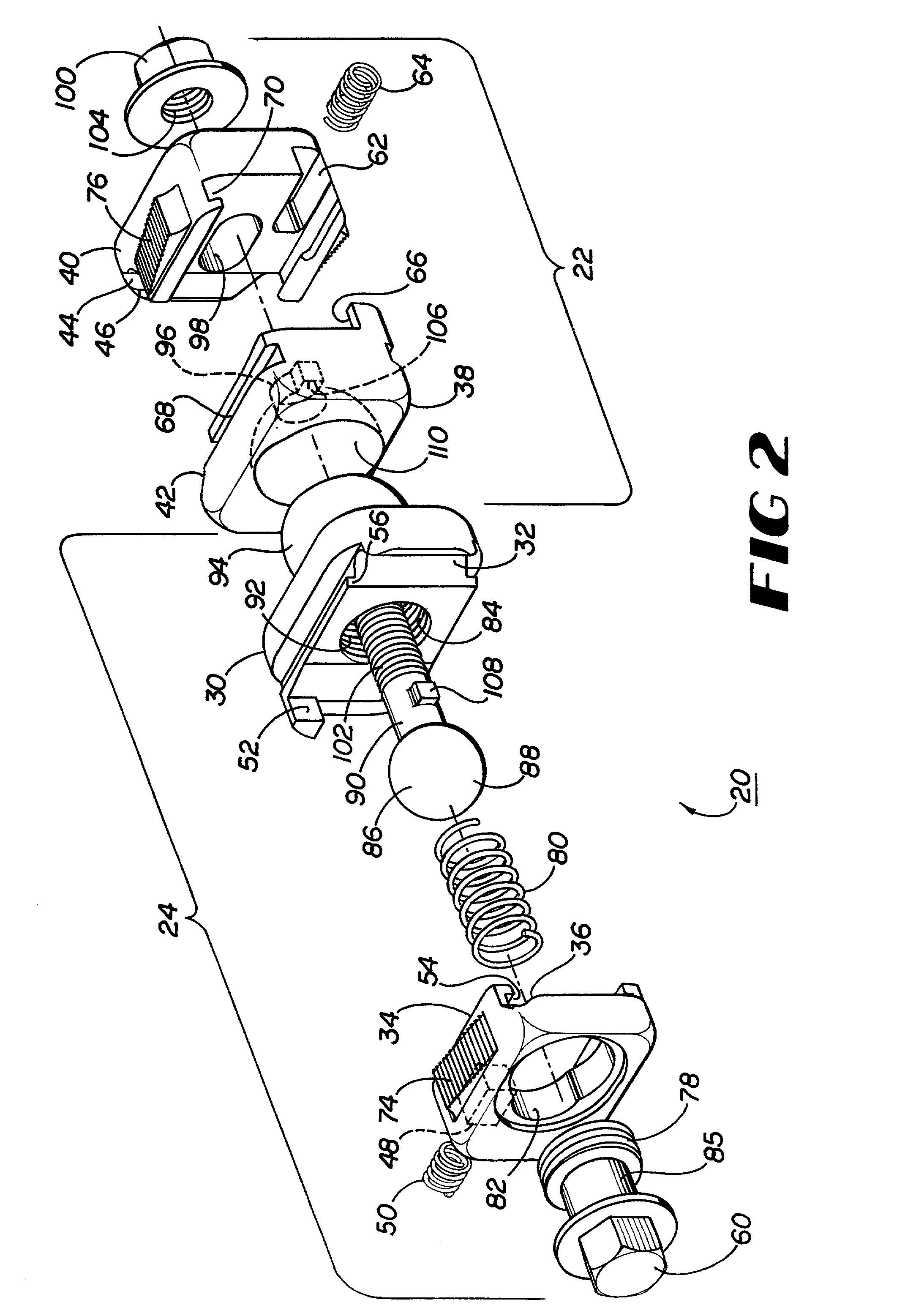
[0027]Methods, systems and devices according to this invention seek to provide improved external fixation, including an improved fixation component allowing an increase in freedom of rotation, independent locking of capture members, a more stable, yet more flexible frame, and cooperation with specialized fixation systems. External fixation systems according to embodiments of this invention may include fixation components designed to retain one or more fixation elements. In general, the fixation components either connect a bar to a bar; a bar to a pin; a bar to a wire; or a bar to a circumferential or half ring. Each fixation component generally includes two capture members, and each capture member includes a base and a head.

[0028]One embodiment of a fixation component according to this invention includes a first capture member and a second capture member connected by a joint. Each capture member includes a channel, which allows attachment of a fixation element from the side. The fir...


PUM


Abstract

An external fixation system having an improved fixation component for constructing a stable, adjustable fixation system that cooperates with other systems, and methods of use thereof.

Description

FIELD OF THE INVENTION[0001]This invention relates generally to methods, systems and devices for orthopedic external fixation and more particularly to an external fixation system having an improved fixation component for constructing a stable, adjustable fixation system that cooperates with other systems, and methods of use thereof.BACKGROUND[0002]Surgeons use external fixation systems regularly to treat certain bony skeletal injuries or conditions, such as acute fractures of the skeleton, soft tissue injuries, delayed union of the skeleton when bones are slow to heal, nonunion of the skeleton when bones have not healed, malunion of broken or fractured bones, congenital deformities resulting in malposition of bone, and bone lengthening, widening, or twisting. Treatment of these conditions often includes stabilization and reduction using an external fixation system. These systems may include a frame comprised of one or more of fixation components and one or more fixation elements. As...

Claims


Application Information

Patent Timeline
Patent Type & Authority Patents(United States)
IPC IPC(8): A61B17/56A61F4/00A61B17/64A61B19/00F16M11/14F16M13/02
CPCA61B17/645A61B17/6466A61B2019/5483A61B2019/267A61B2019/5289A61B19/203A61B2090/3983A61B90/57A61B2090/364A61B90/14
Inventor FERRANTE, JOSEPHJAMES, ANTHONYCASTLEMAN, DAVIDAUSTIN, EDNELSON, KENNETH
Owner SMITH & NEPHEW INC
Why Eureka
Try Eureka