Machine device having superconducting winding and thermosiphon cooling of winding

a technology of superconducting winding and winding cooling, which is applied in the direction of lighting and heating apparatus, magnetic circuit rotating parts, and shape/form/construction of magnetic circuits. it can solve the problems of affecting the operation of the machine, unable to achieve the cooling of refrigerant in the rotor cavity, and relatively low current carrying capacity of the current carrying capacitors

Active Publication Date: 2006-05-23
SIEMENS AG
View PDF9 Cites 21 Cited by
  • Summary
  • Abstract
  • Description
  • Claims
  • Application Information

AI Technical Summary

Benefits of technology

[0015]An aspect of the present invention is to design a machine device having the features mentioned initially such that at least the accumulation of refrigerant, as mentioned, in the central rotor cavity on the refrigerant entry end is prevented in the standby state of the machine.
[0017]The advantages associated with this refinement of the machine device are, in particular, that, even in the case of its machine having a skew in the unfavorable direction depicted, the refrigerant still remains in the entire central interior of the rotor. This is because, when the machine is in the non-operating state (or standby mode), the rotor rotates slowly (so-called “turn”) with the aid of a rotation mechanism. Owing to the helical or spiral design of the refrigerant feed path, in this case the refrigerant is fed from the refrigerant entry end to the opposite end and is thus kept in the entire interior of the rotor cavity. This also makes it possible to control the standby losses, thus making standby operation possible. One precondition for classifying the machine as a main generator is thus fulfilled.
[0018]Further, the device may have a hollow-cylindrical, central rotor cavity having a single- or multi-start feed screw, in particular in the form of an Archimedes screw. Such a screw can easily be installed in the rotor cavity.
[0020]In addition, the pressure may be increased to bring about a short-term pumping action on the liquid refrigerant in the direction of the central rotor cavity by pressure pulses of gaseous refrigerant. Owing to the thermal inertia of the system, it is sufficient if the rotor cavity is subsequently filled with refrigerant at time intervals for a sufficiently short period of time, in particular in a pulsed manner. Even when the rotor has a skew, the superconducting winding is thus reliably cooled in the operating state owing to the central rotor cavity being sufficiently filled.

Problems solved by technology

Conductors known to date, however, have a relatively low current-carrying capacity, in particular in magnetic fields having inductions in the Tesla range.
If it is desired to permit skews of the machine, there is in this case the risk, however, that a region of the tubular pipeline parts between the central rotor cavity and the refrigeration unit will lie at a geodetically lower level than the central rotor cavity.
The result of this is that the refrigerant cannot reach the rotor cavity to be cooled owing to the influence of the force of gravity.
Cooling of the machine and thus its operation would thus no longer be ensured.
A correspondingly inclined arrangement is undesirable in shipbuilding, in particular in the case of larger machine lengths, owing to the large amount of space that is required in this case.Instead of a single-pipe pipeline system, in which the liquid and the gaseous refrigerants flow through identical pipe parts, two-pipe pipeline systems for refrigerant circulation using a thermosiphon effect are also known (cf. for example WO 00 / 13296 A1).
This also requires additional sealing complexity.In principle, the refrigerant may also be forced to circulate by a pumping system.
For this purpose, however, correspondingly high complexity is required in terms of the apparatus, in particular if the refrigerant is intended to be, for example, at a low temperature of, for example, approximately 30 K. Such circulation systems also bring about considerable losses and can scarcely fulfill the service life requirements for shipbuilding with its long maintenance intervals.
In addition, there is the problem that, when the machine is inclined in the longitudinal direction such that the entry end of the refrigerant into the central rotor cavity is at a geodetically lower level than the axially opposite end, the refrigerant flows in the direction of the region of the refrigerant entry end in response to the force of gravity.
It would thus no longer be possible to reliably ensure cooling of the machine and thus its standby operation, since, in this region, thermal losses which are too high and undesirable cooling of the rotor shaft result.

Method used


Image

  • Machine device having superconducting winding and thermosiphon cooling of winding
  • Machine device having superconducting winding and thermosiphon cooling of winding
  • Machine device having superconducting winding and thermosiphon cooling of winding

Examples


Embodiment Construction

[0032]Reference will now be made in detail to the preferred embodiments of the present invention, examples of which are illustrated in the accompanying drawings, wherein like reference numerals refer to like elements throughout.

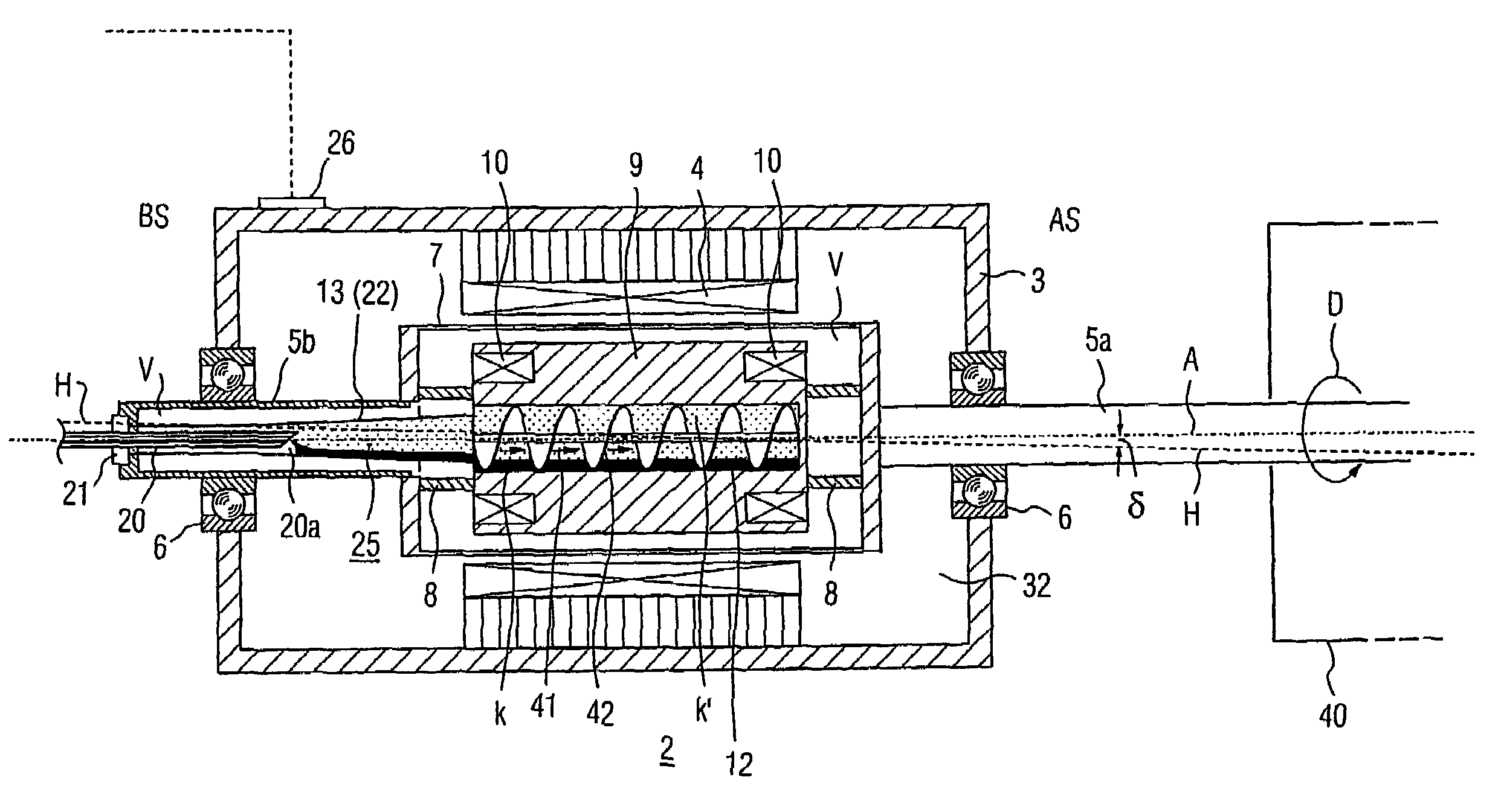
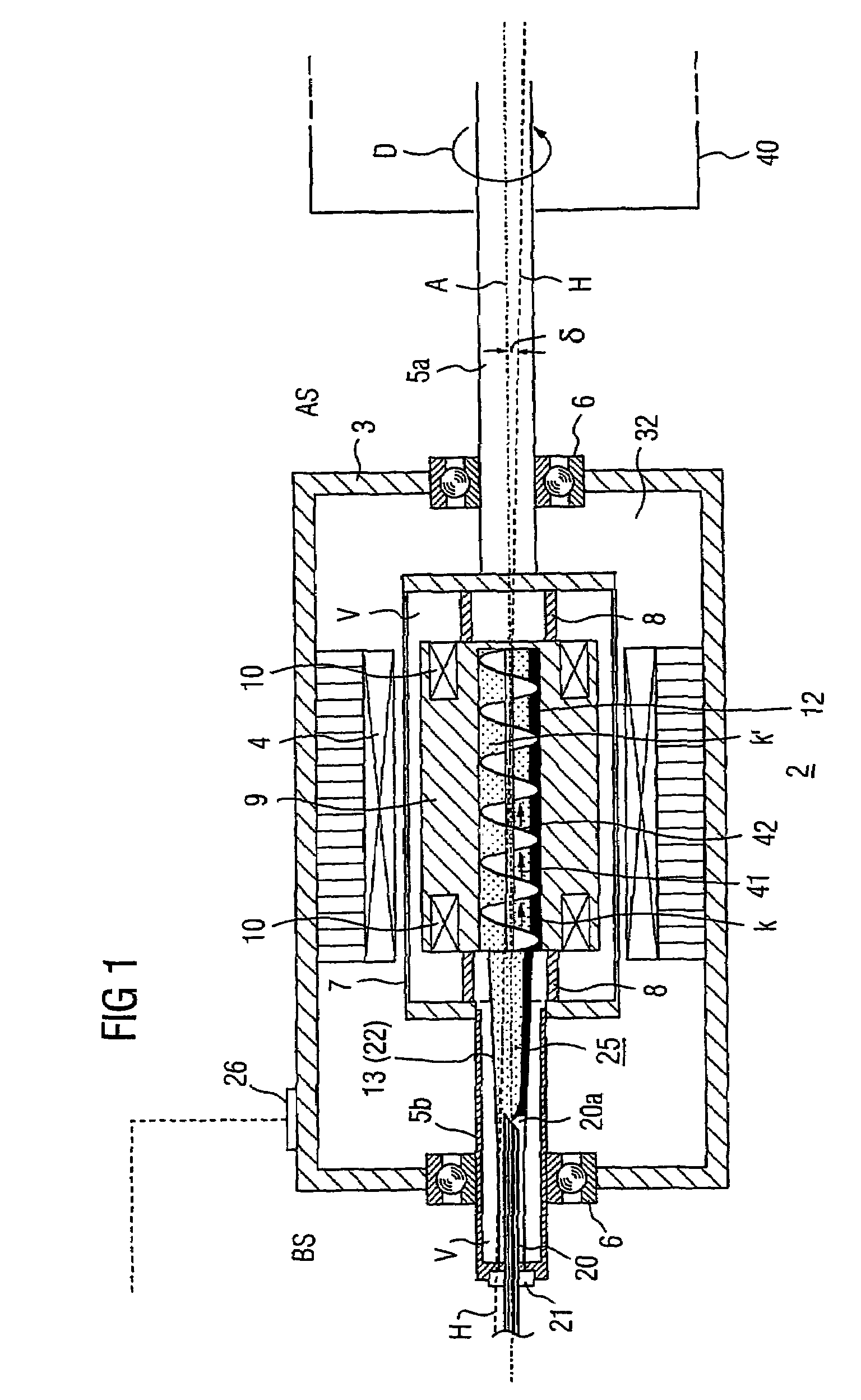
[0033]Machine devices according to the invention each include a machine or a motor and an associated refrigeration unit. The embodiment of this machine described below with reference to the figures may be, in particular, a synchronous motor or a generator. The machine has a rotating, superconducting winding which in principle allows for metallic LTS material (low Tc superconductor material) or oxide HTS material (high Tc superconductor material) to be used. The latter material is used as the basis for the following exemplary embodiments. The winding may include a coil or a system of coils in a two-, four or other multiple arrangement. The basic design of a corresponding synchronous motor is shown in FIG. 1, in which the embodiment of such a machine which is k...


PUM


Abstract

A superconducting device has a rotor rotatable about an axis of rotation and a superconducting winding in a heat conducting winding carrier. The winding carrier has a central cooling agent cavity with a lateral cavity leading out of the winding carrier connected thereto. A cold head associated with a cooling unit is connected to a condenser unit which condenses the cooling agent. A fixed heat tube guiding the cooling agent is coupled to the condenser unit, protruding axially into the co-rotating lateral cavity and is sealed in relation thereto.

Description

CROSS REFERENCE TO RELATED APPLICATIONS[0001]This application is based on and hereby claims priority to German Application No. 103 36 277.0 filed on 7 Aug. 2003, the contents of which are hereby incorporated by reference.BACKGROUND OF THE INVENTION[0002]1. Field of the Invention[0003]The invention relates to a machine device having a rotor, which is mounted such that it can rotate about a rotation axis and has at least one superconducting winding, whose conductors are coupled in a thermally conductive manner to a central, cylindrical rotor cavity which extends in the axial direction and is part of a closed pipeline system, in which there is a refrigerant which circulates using a thermosiphon effect, condensed refrigerant passing into the central rotor cavity, and evaporating refrigerant emerging there from the rotor cavity. A corresponding machine device is described in WO 02 / 43224 A1.[0004]2. Description of the Related Art[0005]Since 1987, metal-oxide superconductor materials havin...

Claims


Application Information

Patent Timeline
Patent Type & Authority Patents(United States)
IPC IPC(8): H02K9/06F25B23/00F28D15/02H02K55/04
CPCH02K55/04F28D15/0266F25B23/006F25B2700/04Y02E40/625Y02E40/60
Inventor FRANK, MICHAELKUHN, ADOLFVAN HASSELT, PETER
Owner SIEMENS AG
Why Eureka
Try Eureka