Image input device with rotatable image pickup unit

Inactive Publication Date: 2006-05-23
CANON KK
View PDF27 Cites 17 Cited by
  • Summary
  • Abstract
  • Description
  • Claims
  • Application Information

AI Technical Summary

Benefits of technology

[0028]It is, therefore, an object of the present invention to provide an image inputting device, which has superior operability to a conventional one, has a

Problems solved by technology

However, the conventional document camera has a relatively low mechanical strength in its collapsed state.
Another problem is that the photographing lens 108 is more easily susceptible to flaws and contaminations.
However, the necessity of such a dedicated protective member is disadvantageous in that the structure of the document camera is more complicated and the number of extra parts is increased.
In that situation, there is a risk that the electrical signal line is more likely to break with repeated operations of extending and contracting the upper camera arm 106 and t

Method used


Image

  • Image input device with rotatable image pickup unit
  • Image input device with rotatable image pickup unit
  • Image input device with rotatable image pickup unit

Examples


first embodiment

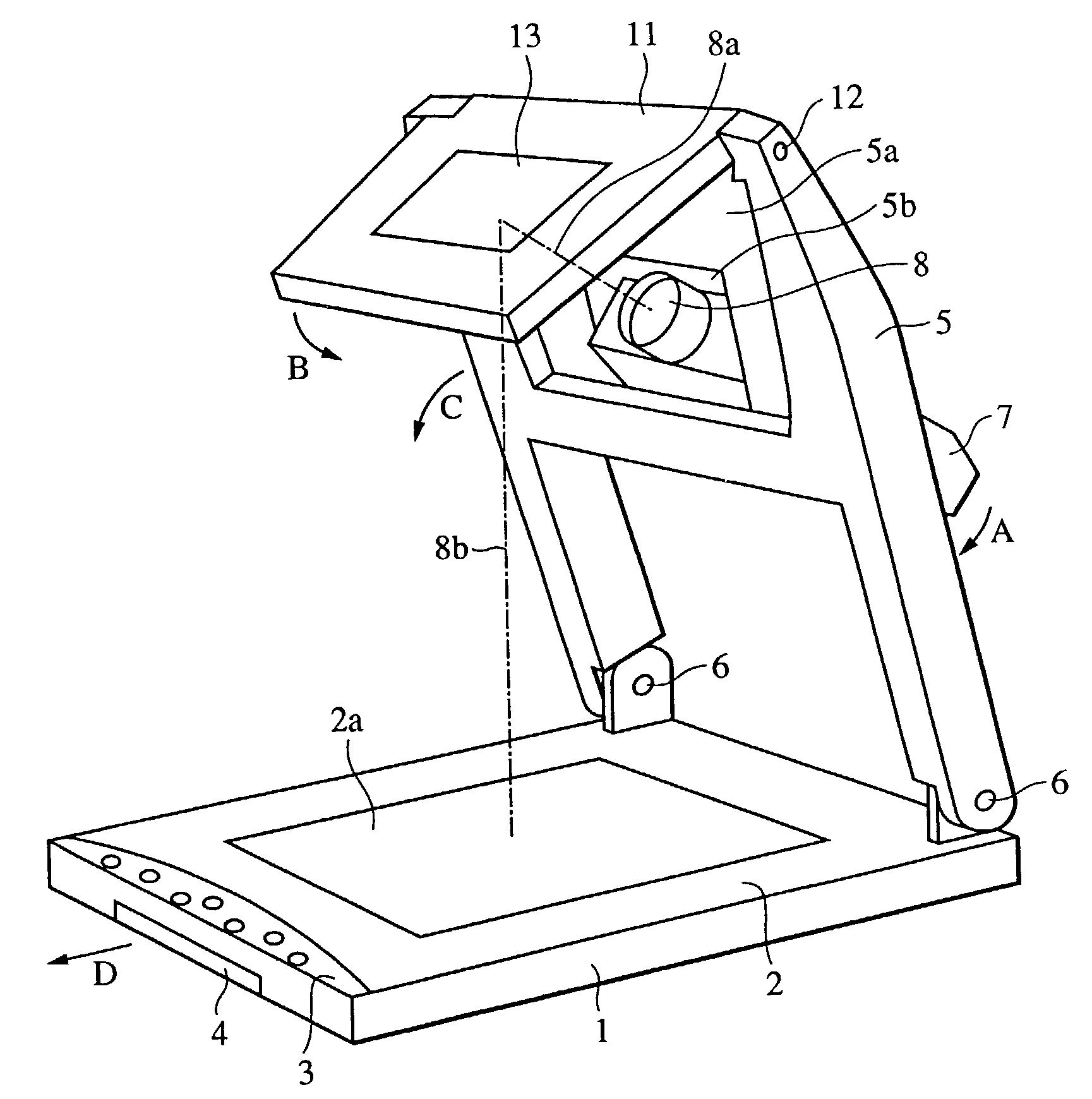
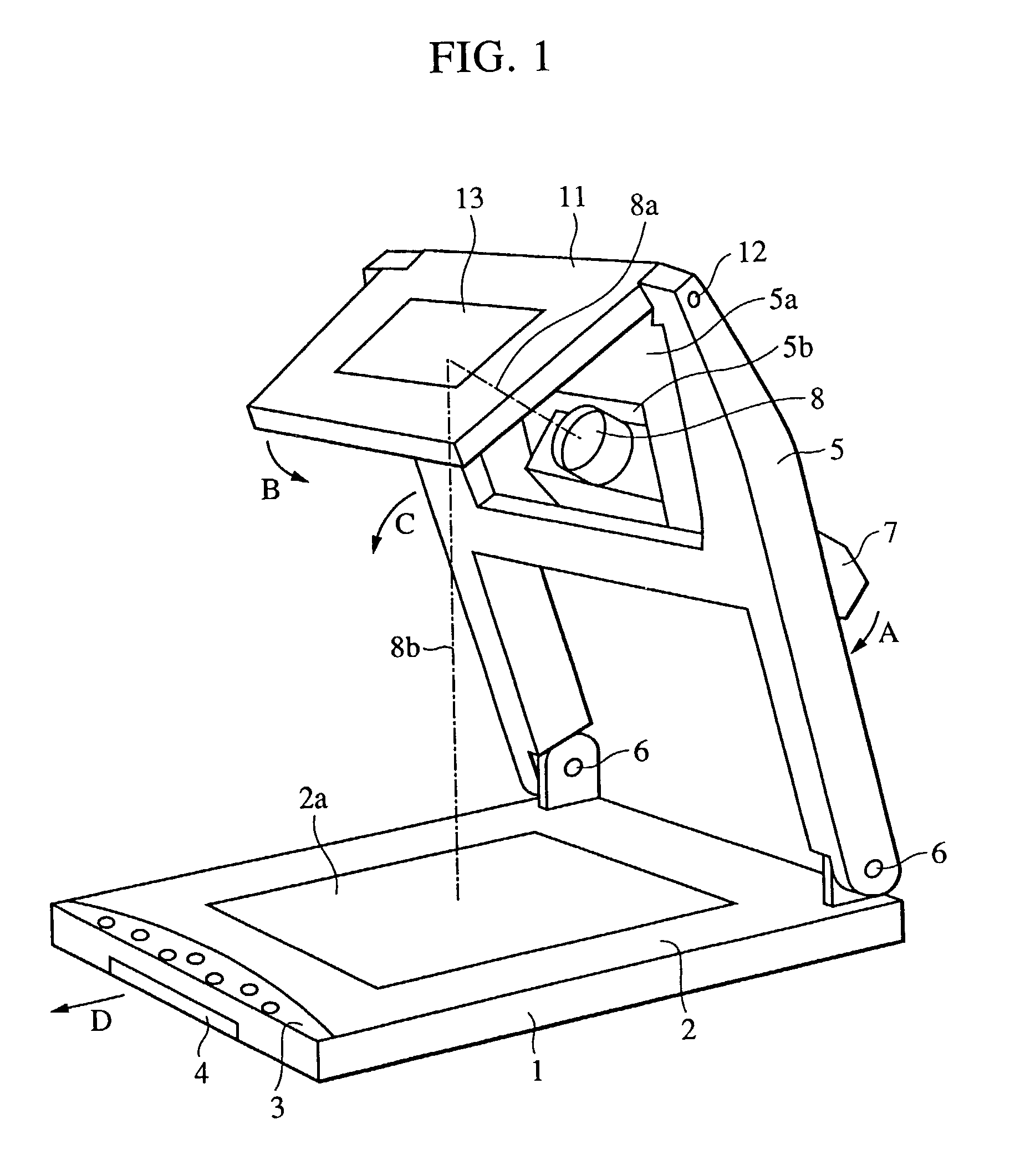
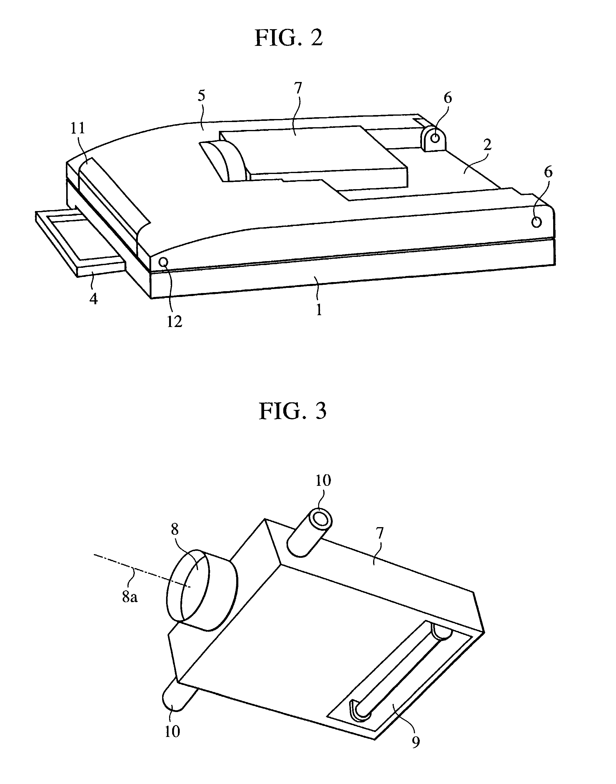
[0058]FIGS. 1 to 6 show a construction of an image inputting device (document camera) according to a first embodiment of the present invention. FIGS. 1 and 4 show the image inputting device in its photographing state. FIGS. 2 and 6 show the image inputting device in its collapsed (folded-up) state. FIG. 3 shows an image pickup unit of the image inputting device. FIG. 5 shows the image inputting device during a shift from the photographing state to the collapsed (folded-up) state.

[0059]The first embodiment of the present invention will be described below with reference to FIGS. 1 to 6. In these drawings, a document resting surface 2 is formed on a document stage unit (base) 1, and a document (object to be photographed) 2a is placed on the document resting surface 2.

[0060]A control panel (console) 3 manipulated for instructing the operation of the image inputting device is made up of electrical switches, etc. and is disposed on an upper surface of the document stage unit 1 in its fron...

second embodiment

[0105]FIGS. 7 to 11 show an image inputting device (document camera) according to a second embodiment of the present invention. FIGS. 7 and 9 show the image inputting device in its photographing state. FIGS. 8 and 11 show the image inputting device in its collapsed (folded-up) state. FIG. 10 shows the image inputting device during a shift from the photographing state to the collapsed (folded-up) state.

[0106]Note that, in this second embodiment described with reference to FIGS. 7 to 11, components in common to the first embodiment described above with reference to FIGS. 1 to 6 are denoted by the same symbols as those in the first embodiment.

[0107]While the document illumination unit 9 is integrally provided with the image pickup unit 7 in the above-described first embodiment, a document illumination unit 22 is mounted to the movable holding unit 5 in an unfolding and collapsing manner separately from the image pickup unit 7.

[0108]In FIGS. 7 to 11, the document illumination unit 22 ha...

third embodiment

[0151]A third embodiment of the present invention will be described below with reference to FIGS. 12 to 16.

[0152]FIG. 12 is a perspective view of an image inputting device (document camera) according to a third embodiment of the present invention in its photographing state. FIGS. 13 and 14 are side views of the image inputting device of FIG. 12 in the photographing state. FIG. 15 is a side view of the image inputting device of FIG. 12 during a shift from the photographing state to a collapsed state (folded-up state). FIG. 16 is a side view of the image inputting device of FIG. 13 in the collapsed state (folded-up state).

[0153]A perspective view of the image inputting device of FIG. 12 in the collapsed state (folded-up state) is the same as that shown in FIG. 2 representing the first embodiment, and hence it is omitted here.

[0154]Note that, in this third embodiment described with reference to FIGS. 12 to 16, components in common to the first embodiment described above with reference ...


PUM


Abstract

An image inputting device comprises a base having an object resting surface on which an object rests, an image pickup unit, a reflecting unit having a reflecting surface for reflecting a light from the object and introducing the light to the image pickup unit, and a holding unit disposed on the base to be rotatable about a first axis parallel to the object resting surface. The image pickup unit is rotatable about a second axis disposed on the holding unit, and the reflecting unit is rotatable about a third axis disposed on the holding unit.

Description

BACKGROUND OF THE INVENTION[0001]1. Field of the Invention[0002]The present invention relates to an image inputting device for picking up an image of an object to be photographed, which is placed on a stage or base.[0003]2. Description of the Related Art[0004]The so-called document camera is known as an image inputting device for picking up an image of an object to be photographed, e.g., a document, placed on a stage.[0005]A conventional document camera (image inputting device) will be described below with reference to FIGS. 17 and 18. FIG. 17 shows the document camera in a state of photographing a document, and FIG. 18 shows the document camera during a collapsing, or folding, step.[0006]In those drawings, a document stage 102 is formed on a document stage unit 101, and a document 102a is placed on the document stage 102. A control panel 103 manipulated for instructing the operation of the document camera is made up of electrical switches, etc.[0007]A rotary shaft 105a is provided ...

Claims


Application Information

Patent Timeline
IPC IPC(8): H04N5/225G03B27/52H04N1/46H04N1/195
CPCH04N1/195H04N1/19594H04N2201/045H04N2201/0436H04N2201/0096
Inventor NAGANO, MASATOSHI
Owner CANON KK
Why Eureka
Try Eureka