Lithographic apparatus and device manufacturing method

a technology of lithographic apparatus and manufacturing method, which is applied in the direction of photomechanical apparatus, printers, instruments, etc., can solve the problems of bubbles in immersion lithography, unusable and unpredictable effects, and the existence of bubbles in immersion liquid, so as to reduce the effect of bubbles

Active Publication Date: 2006-05-23
ASML NETHERLANDS BV
View PDF85 Cites 166 Cited by
  • Summary
  • Abstract
  • Description
  • Claims
  • Application Information

AI Technical Summary

Benefits of technology

[0011]It is an aspect of the present invention to reduce the effect of bubbles in immersion liquid on the imaging quality in immersion lithography.
[0013]In this way, it is possible to apply a force on bubbles in the immersion liquid in a direction either towards or away from the first object. This is because bubbles in the immersion liquid will have a natural electrokinetic potential which is a potential difference between the surface of the bubble and the fully dissociated ionic concentration in the body of the liquid. Thus, by choosing the first electrical potential to be either the same or opposite polarity to the electrokinetic potential of the bubble it can be determined whether the bubble moves towards or away from the first object. Thus, this system can be used to move bubbles in the immersion liquid to places where their effect on the imaging quality of the apparatus is minimized. The present invention works in the same way on small particles as it does on bubbles.
[0014]Preferably, the first object forms a border of the space so that the positions of the bubbles in the immersion liquid in the space can be controlled. Alternatively, the first object can be in contact with the immersion liquid in a supply channel upstream of the space. In this way it is possible to avoid the generation of excessive electrical potential fields in the space which might be deleterious to sensors in the space or might be difficult to arrange for because of the limited space for objects under the projection system.
[0015]It is desirable to have a second power source or voltage to apply a second electrical potential to a second object in contact with the immersion liquid. In this way, the force on the bubbles may be increased as the first electrical potential could be made effective to repel the bubbles whilst the second electrical potential could be made effective to attract the bubbles, or vice versa.
[0017]In another embodiment, the first object still forms a border of the space but is positioned distal from the optical axis of the apparatus. In this way bubbles can be moved away from the optical axis of the apparatus so that the liquid through which imaging is actually taking place is substantially free of bubbles.

Problems solved by technology

This requires additional or more powerful motors and turbulence in the liquid may lead to undesirable and unpredictable effects.
A difficulty in immersion lithography has been found to be the existence of bubbles in the immersion liquid.
These bubbles can be of any size, but bubbles of the order of a few μm have presented a particular problem.

Method used


Image

  • Lithographic apparatus and device manufacturing method
  • Lithographic apparatus and device manufacturing method
  • Lithographic apparatus and device manufacturing method

Examples


Embodiment Construction

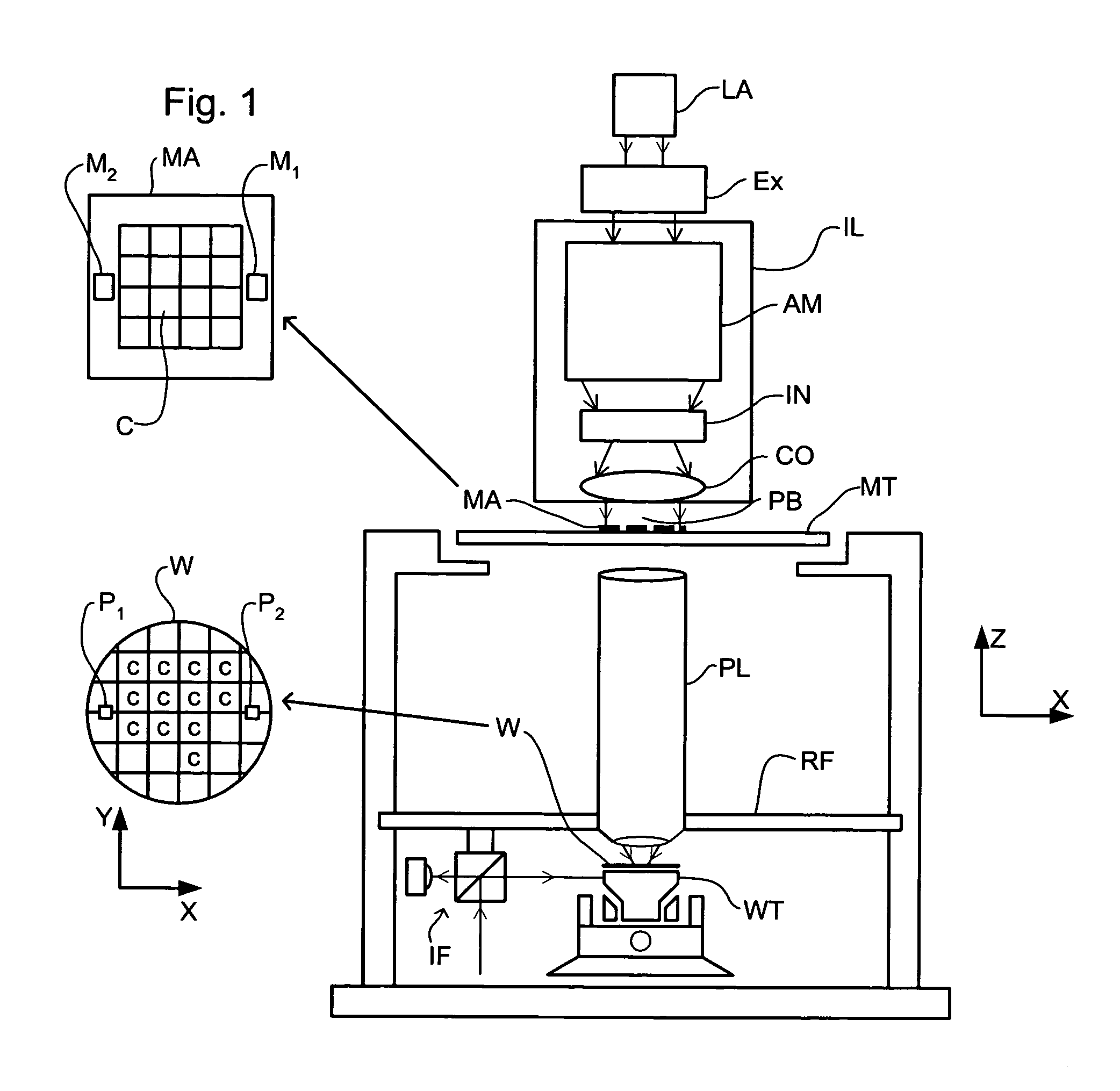
[0032]FIG. 1 schematically depicts a lithographic apparatus according to a particular embodiment of the invention. The apparatus includes an illumination system (illuminator) IL for providing a projection beam PB of radiation (e.g. UV radiation). A first support structure (e.g. a mask table) MT is configured to support a patterning structure (e.g. a mask) MA and is connected to a first positioning device PM that accurately positions the patterning structure with respect to a projection system. A substrate table (e.g. a wafer table) WT is configured to hold a substrate (e.g. a resist-coated wafer) W and is connected to a second positioning device PW that accurately positions the substrate with respect to the projection system. The projection system (e.g. a refractive projection lens) PL images a pattern imparted to the projection beam PB by the patterning structure MA onto a target portion C (e.g. including one or more dies) of the substrate W.

[0033]As here depicted, the apparatus is...


PUM

PropertyMeasurementUnit
electrical potentialaaaaaaaaaa

Abstract

An immersion lithographic apparatus includes a voltage generator or power source that applies a potential difference to an object in contact with the immersion liquid such that bubbles and / or particles in the immersion liquid are either attracted or repelled from that object due to the electrokinetic potential of the surface of the bubble in the immersion liquid.

Description

BACKGROUND OF THE INVENTION[0001]1. Field of the Invention[0002]The present invention relates to a lithographic apparatus and a device manufacturing method.[0003]2. Description of the Related Art[0004]A lithographic apparatus is a machine that applies a desired pattern onto a target portion of a substrate. Lithographic apparatus can be used, for example, in the manufacture of integrated circuits (ICs). In that circumstance, a patterning structure, such as a mask, may be used to generate a circuit pattern corresponding to an individual layer of the IC, and this pattern can be imaged onto a target portion (e.g. including part of one or several dies) on a substrate (e.g. a silicon wafer) that has a layer of radiation-sensitive material (resist). In general, a single substrate will contain a network of adjacent target portions that are successively exposed. Known lithographic apparatus include so-called steppers, in which each target portion is irradiated by exposing an entire pattern o...

Claims


Application Information

Patent Timeline
Patent Type & Authority Patents(United States)
IPC IPC(8): G03B27/52G03F7/20H01L21/027
CPCG03F7/70341G03F7/2041G03F7/70908
Inventor DUINEVELD, PAULUS CORNELISDIRKSEN, PETERKOLESNYCHENKO, ALEKSEY YURIEVICHVAN SANTEN, HELMAR
Owner ASML NETHERLANDS BV
Why Eureka
Try Eureka