Wavelength division multiplexing receiver for wavelength tracking

a wavelength tracking and wavelength division technology, applied in the field of wavelength tracking receivers, can solve the problems of increasing the complexity of the transmitter, and limiting the number of channels that can be supported by the wdm system

Active Publication Date: 2006-05-23
AVAGO TECH INT SALES PTE LTD
View PDF2 Cites 5 Cited by
  • Summary
  • Abstract
  • Description
  • Claims
  • Application Information

AI Technical Summary

Benefits of technology

[0010]The WDM receiver generates more detection signals than the number of channels in the optical input signal. This enables the WDM receiver to detect the optical signals that constitute the optical input signal, even when the optical signals are generated by sources whose wavelengths are offset from the center

Problems solved by technology

Since only a finite portion of the spectral bandwidth of current optical fiber can be used to transmit optical signals, the bandwidth required for each channel limits the number of channels that can be supported by a WDM system.
However, in this first approach each channel generally requires about 15 nm of bandwidth.
Unfortunately, using temperature-controlled laser sources increases the complexity of th

Method used


Image

  • Wavelength division multiplexing receiver for wavelength tracking
  • Wavelength division multiplexing receiver for wavelength tracking
  • Wavelength division multiplexing receiver for wavelength tracking

Examples


first embodiment

[0022]WDM Receiver

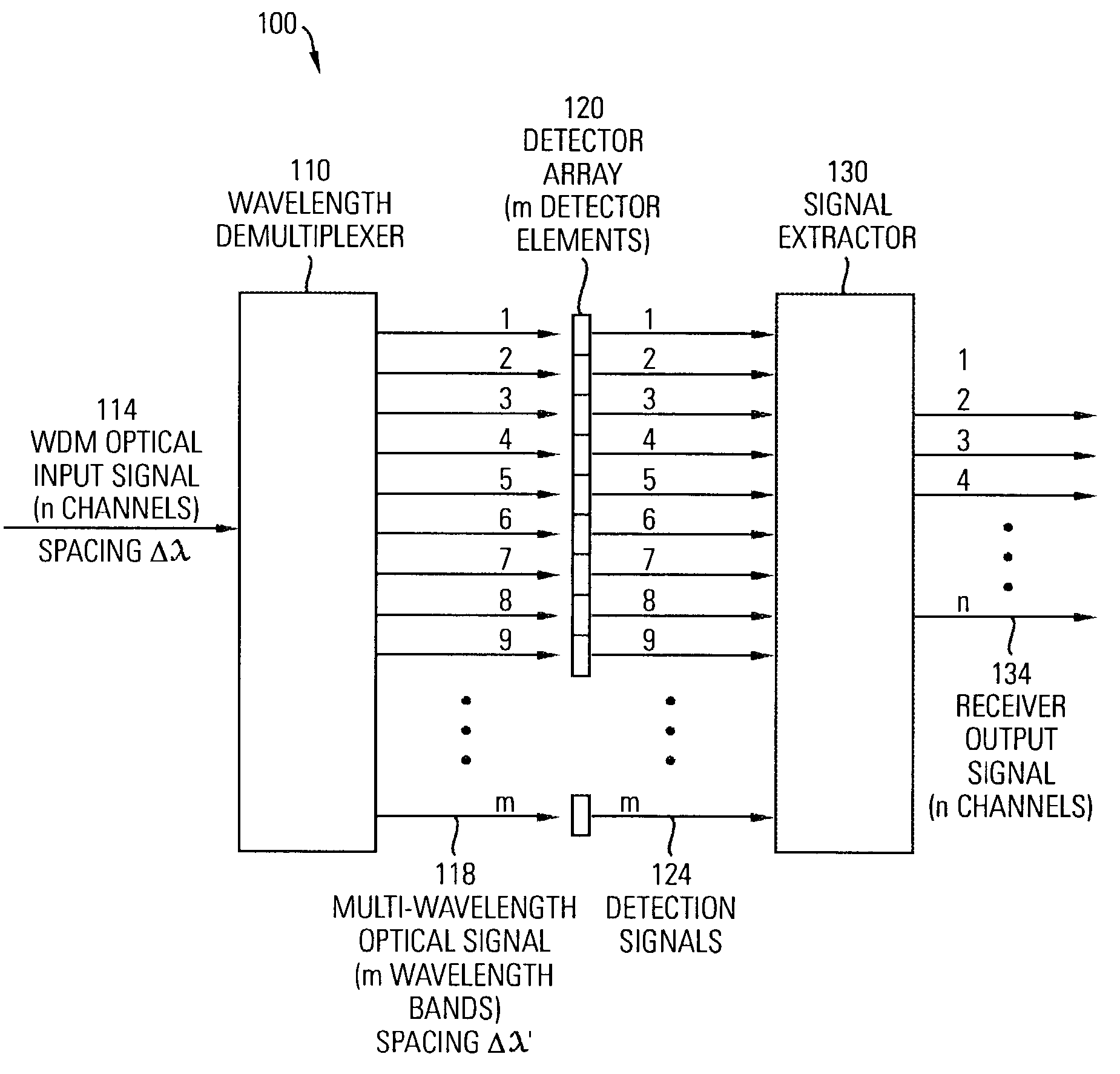
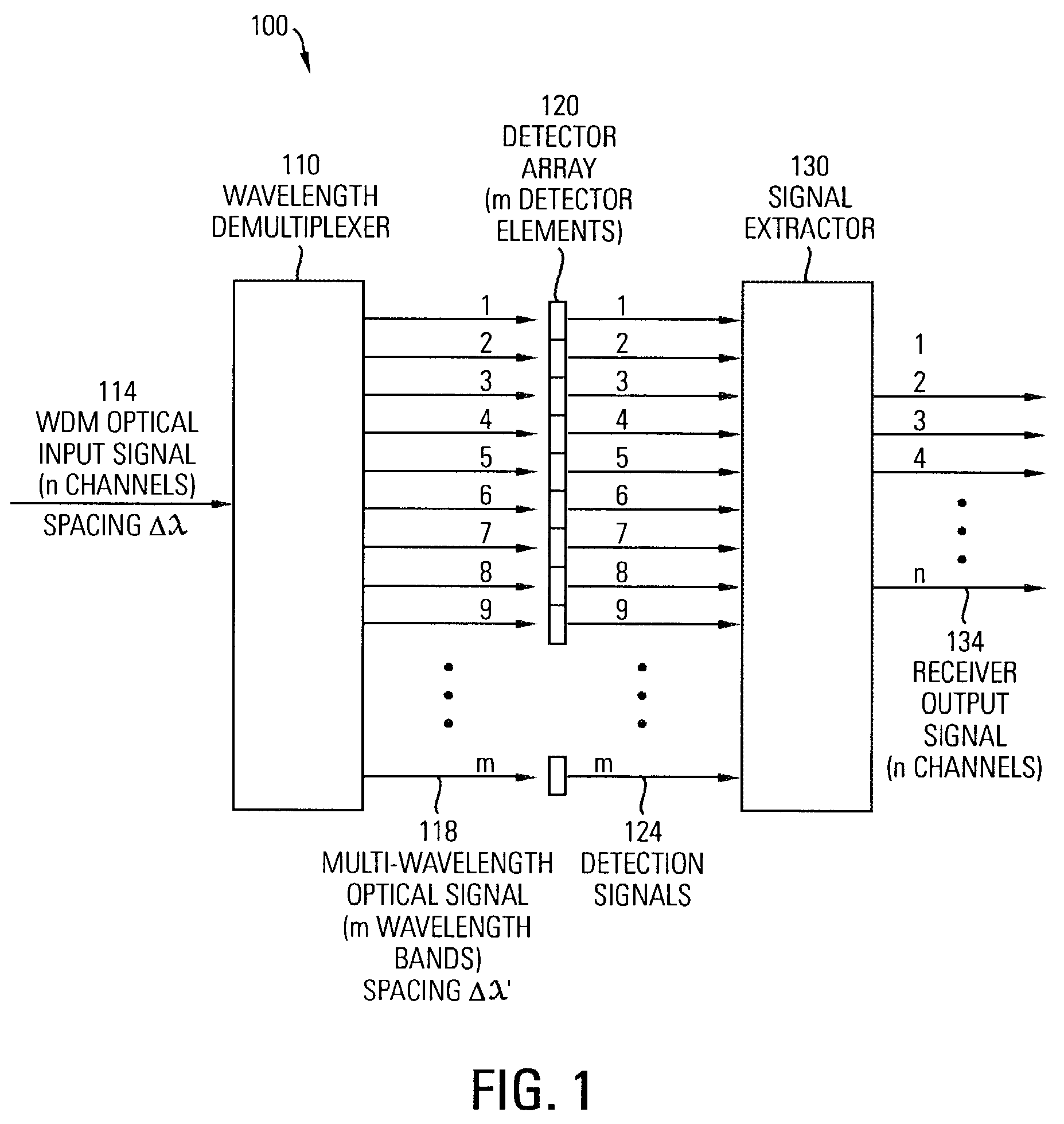
[0023]FIG. 1 is a block diagram illustrating a first embodiment 100 of a wavelength division multiplexing (WDM) receiver 100 according to the invention. The WDM receiver 100 includes a wavelength demultiplexer 110 for receiving WDM optical input signal 114. The wavelength demultiplexer 110 generates a multi-wavelength optical signal 118 from the WDM optical input signal.

[0024]The WDM optical input signal 114 is an n-channel optical signal. Each channel has a center wavelength and adjacent channels are separated in wavelength by a channel spacing of delta lambda (Δλ). Optical signals having mutually different wavelengths are assigned to the channels of the WDM optical input signal. There is no requirement or implication that, at a given time, an optical signal be present in every channel of the WDM optical input signal. Moreover, the wavelengths of one or more of the optical signals may be offset from the center wavelengths of the channels to which the optical signa...

second embodiment

[0044]WDM Receiver

[0045]FIG. 5 is a block diagram illustrating a second embodiment 300 of a WDM receiver according to the invention. The WDM receiver 300 includes a splitter 304 for receiving WDM optical input signal 314 and for splitting the WDM optical input signal into two optical input signal components of substantially equal amplitude, e.g., a first optical signal component and a second optical signal component. The WDM optical input signal is an n-channel optical signal with a channel spacing of delta lambda (Δλ), as described above.

[0046]The WDM receiver 300 also includes a first wavelength demultiplexer 310 that is coupled to the splitter 304 to receive one of the optical input signal components, e.g., the first optical signal component. The first wavelength demultiplexer generates a first multi-wavelength optical signal 318 in response to the first optical signal component.

[0047]The first multi-wavelength optical signal 118 is an optical signal composed of a number m of wav...


PUM


Abstract

The WDM receiver includes a wavelength demultiplexer, a detector array and a signal extractor. The wavelength demultiplexer receives an n-channel optical input signal and transmits the n-channel optical input signal to m optical outputs. Each of the optical outputs receives a wavelength band centered at a different wavelength. The wavelength bands have a center-to-center wavelength spacing of Δλ′. The detector array is composed of m detector elements coupled to the wavelength demultiplexer. Each of the detector elements generates a detection signal in response to light received from one of the optical outputs of the wavelength demultiplexer. The signal extractor receives the detection signals from the detector array and converts the detection signals to an n-channel receiver output signal, each channel of which corresponds to a different one of the n channels of the optical input signal. The WDM receiver is able to detect optical signals that are closely spaced in wavelength, even when the optical signals have off-center of varying wavelengths.

Description

FIELD OF THE INVENTION[0001]The invention relates generally to wavelength division multiplexing (WDM) receivers, and more particularly, to a wavelength division multiplexing (WDM) receiver for wavelength tracking.BACKGROUND OF THE INVENTION[0002]Optical communication systems provide an important way for transferring large amounts of data and other signals at high speeds. An important component in these optical communication systems is an optical transceiver. On the transmission side, the optical transceiver functions to translate an electrical signal representing an information signal (e.g., a digital information signal in the form of 1s and 0s) into an optical signal suitable for transmission via a transmission medium (e.g., an optical fiber). On the reception side, the optical transceiver converts the received optical signal back into an electrical signal that represents the original information signal. An important component in the optical transceiver design is the transmitter fo...

Claims


Application Information

Patent Timeline
IPC IPC(8): H04J14/02H04B10/158
CPCH04J14/02
Inventor LEMOFF, BRIAN E.PETERS, FRANK H.
Owner AVAGO TECH INT SALES PTE LTD
Why Eureka
Try Eureka