Cylinder head with integrated exhaust manifold

a cylinder head and exhaust manifold technology, applied in the direction of cylinders, mechanical equipment, machines/engines, etc., can solve the problems of increased manufacturing and assembly costs, more complex and inefficient traditional ices, and more expensive, so as to improve the warm-up rate of catalytic converters, improve the geometry of the exhaust manifold, and improve the efficiency of manufacturing and assembly

Inactive Publication Date: 2006-05-30
GM GLOBAL TECH OPERATIONS LLC
View PDF2 Cites 39 Cited by
  • Summary
  • Abstract
  • Description
  • Claims
  • Application Information

AI Technical Summary

Benefits of technology

[0007]An improved exhaust manifold geometry is achieved and assembly of the cylinder head is made easier. Bends in exhaust ports of the exhaust manifold occur much earlier along the length of the exhaust port than was traditionally achievable. The bends in a traditionally designed exhaust port do not occur until after a substantially long straight section of the exhaust port. As a result, the exhaust manifold geometry of the present invention enables improved catalytic converter warm-up rates, improved heater warm-up performance and reduced exhaust flow restriction.
[0008]Overall cost is reduced as a result of reduced complexity of the exhaust manifold. Further, for V-shaped ICEs, identical cylinder head castings can be used for both sides of the ICE. This reduces the tooling and variety of castings required because the identical cylinder heads can be used for both sides of the ICE.

Problems solved by technology

Traditional ICEs are more complex and inefficient than desired, making manufacture and assembly more difficult and more expensive.

Method used


Image

  • Cylinder head with integrated exhaust manifold
  • Cylinder head with integrated exhaust manifold
  • Cylinder head with integrated exhaust manifold

Examples


Embodiment Construction

[0019]The following description of the preferred embodiments is merely exemplary in nature and is in no way intended to limit the invention, its application, or uses.

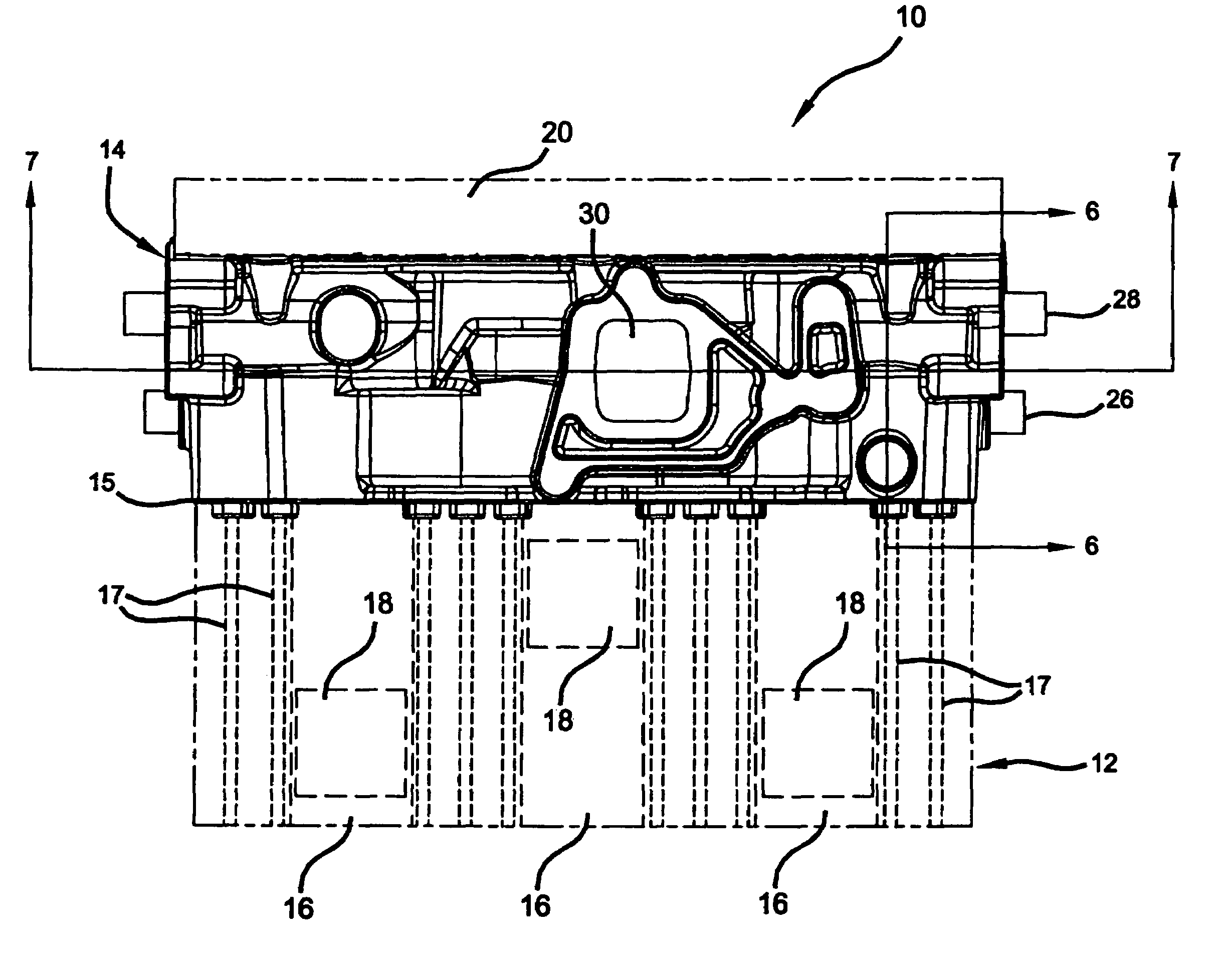
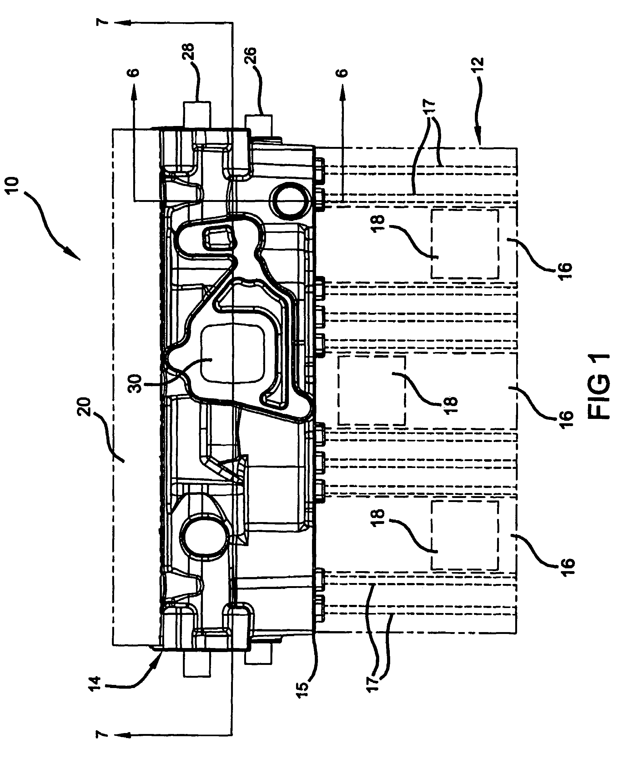
[0020]Referring now to FIG. 1, a schematic illustration of an internal combustion engine (ICE) 10 is shown. The ICE 10 includes a cylinder block 12 (shown schematically in phantom) with a cylinder head 14 secured thereto. A gasket 15 is disposed between the cylinder block 12 and the cylinder head 14. The cylinder block 12 includes a series of cylinders 16 bored therein. The number of cylinders 16 in the ICE 10 can vary depending on the particular design. For example, the ICE can include 3, 4, 6, 7, 10 or 12 cylinders. A piston 18 is slidably disposed within each of the cylinders 16. The pistons 18 are connected to a camshaft (not shown) by respective cams (not shown). An intake manifold (not shown) enables a flow of air into the cylinders 16 to mix with fuel injected therein. This fuel / air mixture is combusted within th...


PUM


Abstract

A cylinder head for an internal combustion engine (ICE) includes a lower cooling jacket, an upper cooling jacket and an exhaust manifold disposed therebetween. The exhaust manifold enables exhaust of combustion gas from cylinders of the ICE. The lower cooling jacket has coolant flow paths in fluid communication with coolant flow paths of a cylinder block of the ICE. Coolant flow paths of the upper cooling jacket are in fluid communication with those of the lower cooling jacket through one of a plurality of passages. The passages can be selectively plugged to define coolant flow direction through the cylinder head. The upper and lower cooling jackets are in heat exchange relationship with surfaces of the exhaust manifold to cool exhaust gas flowing therethrough.

Description

CROSS-REFERENCE TO RELATED APPLICATIONS[0001]This application claims the benefit of U.S. Provisional Application No. 60 / 514,628, filed on Oct. 27, 2003. The disclosure of the above application is incorporated herein by reference.FIELD OF THE INVENTION[0002]The present invention relates to internal combustion engines, and more particularly to a cylinder head with integrated exhaust manifold.BACKGROUND OF THE INVENTION[0003]An internal combustion engine (ICE) combusts fuel to produce driving force. The ICE typically includes a series of reciprocating pistons that drive a crankshaft. The pistons are slidably disposed within cylinders formed in a cylinder block. A cylinder head is secured to the cylinder block sealing the pistons within the cylinders.[0004]The cylinder head is the detachable part of the top of the ICE that contains spark plugs, inlet valves, exhaust valves and may contain a camshaft. It seals the cylinder and forms the top of the combustion chamber. Generally, the cylin...

Claims


Application Information

Patent Timeline
Patent Type & Authority Patents(United States)
IPC IPC(8): F01N7/06F02F1/36F01N13/06F01N3/04F01N13/10
CPCF01N3/043F01N13/10Y02T10/20Y02T10/12
Inventor HAYMAN, ALAN W.BAKER, RODNEY E.
Owner GM GLOBAL TECH OPERATIONS LLC
Why Eureka
Try Eureka