Suspension restraint devices

a technology of suspension restraint and suspension device, which is applied in the direction of shock absorbers, steering devices, cycle equipments, etc., can solve the problem of becoming difficult to wheelie the motorcycle of the star

Inactive Publication Date: 2006-05-30
MARET KEVIN
View PDF11 Cites 13 Cited by
  • Summary
  • Abstract
  • Description
  • Claims
  • Application Information

AI Technical Summary

Benefits of technology

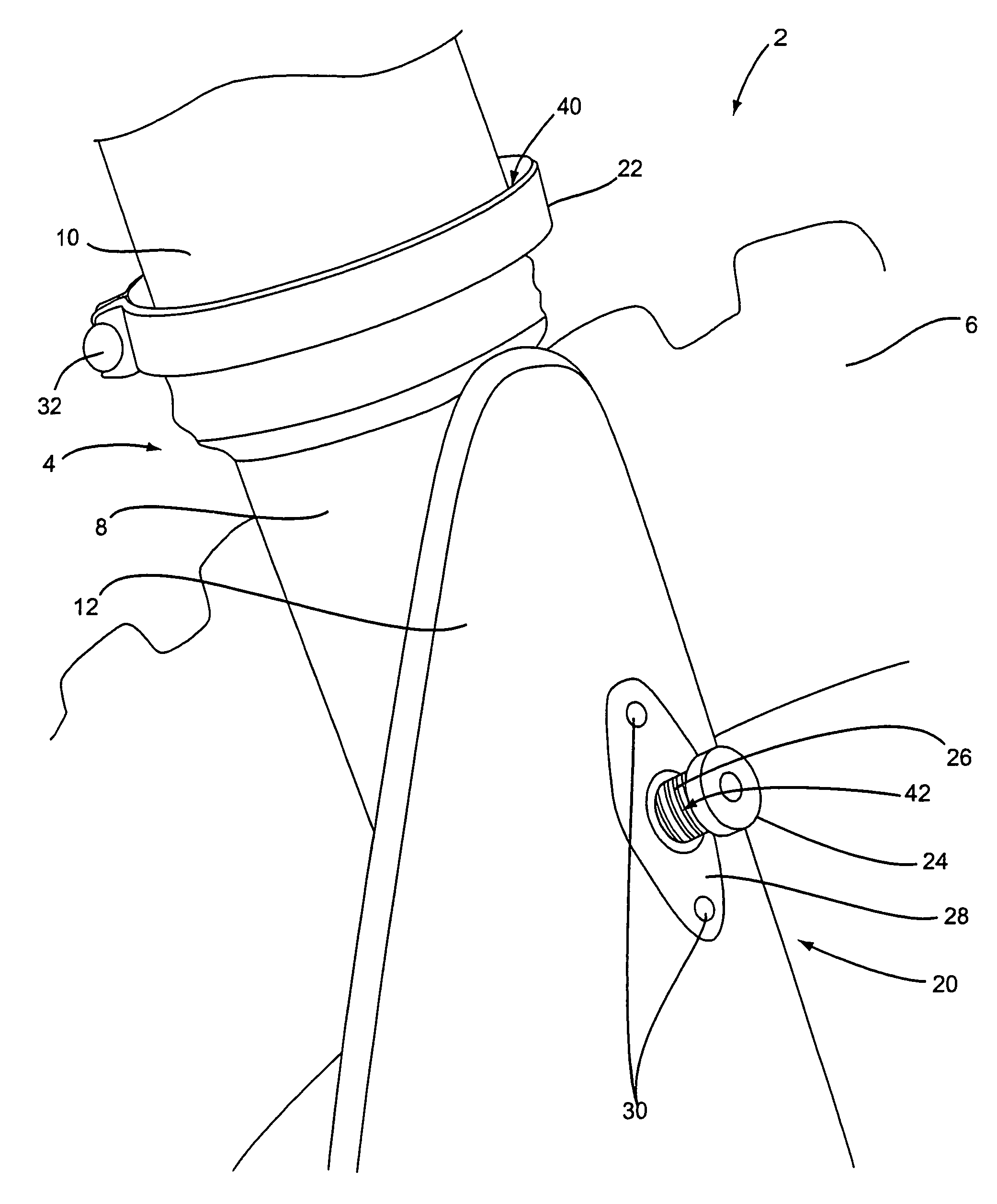
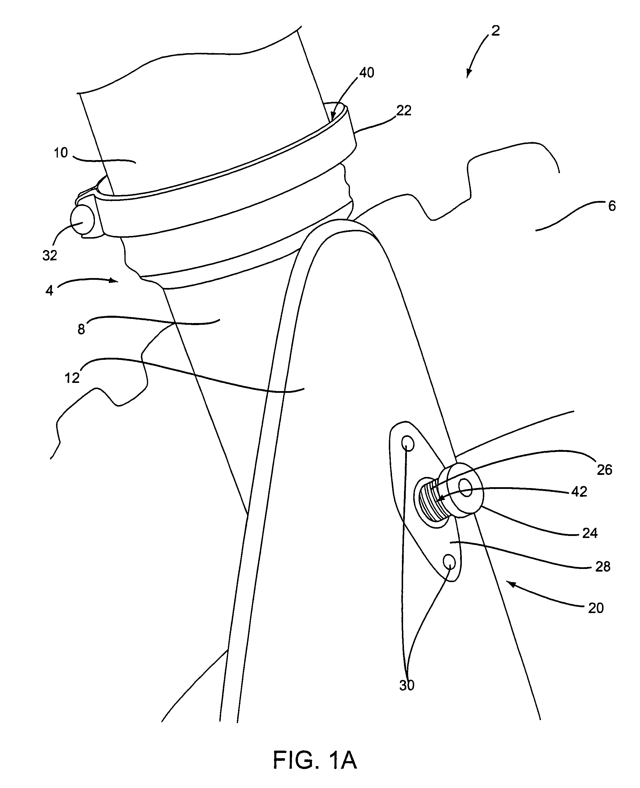
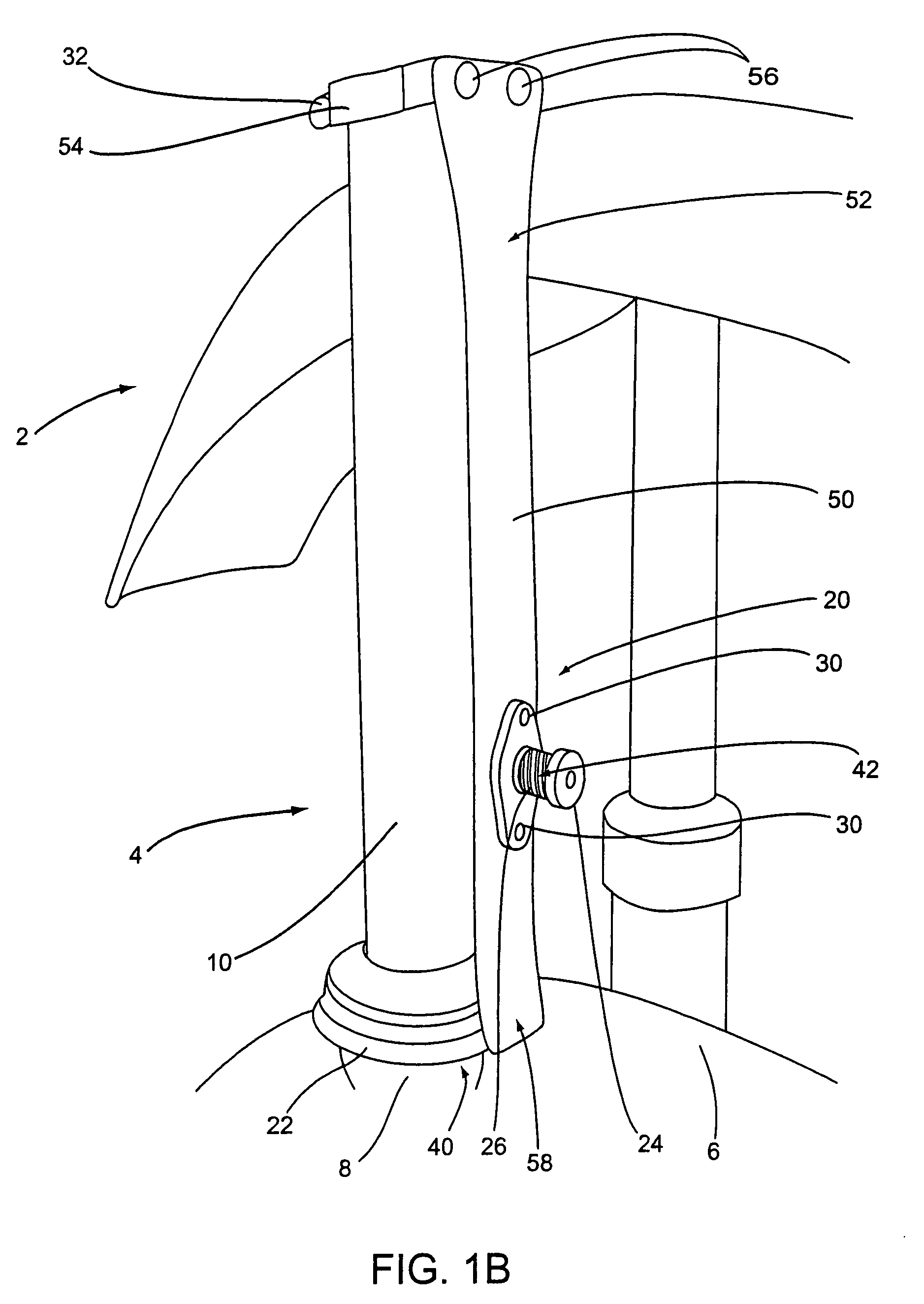
[0007]One variation of the invention contemplates providing a plurality (preferably only two) push buttons incorporated in a single lock-down device. Alternately, or additionally, the fork interface member may include a plurality of engagement positions or multiple fork-side engagement members may be provided. However configured, such provisions allow a rider to choose the button and / or fork interface position that is optimal for given track conditions.
[0008]As conditions change throughout the day, a rider might choose to select a setup with a different degree for fork compression and temporary lockdown. For example, with a two-button device, if the conditions are tacky in the first moto, then the rider should choose the lower button. If the conditions dry out throughout the days racing, the rider can use the upper button for the 2nd moto. If the start is concrete, then the rider can use the upper button all the time—or no lockdown. The rider can easily try both positions before each moto and see which works best without switching fork guards and purchasing extra button devices. The invention includes such methodology in addition to the various devices described.

Problems solved by technology

In any case, thus locked, it becomes difficult to wheelie the motorcycle of the start while holding the throttle wide open.

Method used


Image

  • Suspension restraint devices
  • Suspension restraint devices
  • Suspension restraint devices

Examples


Embodiment Construction

[0017]It is to be understood that this invention is not limited to particular variations set forth and may, of course, vary. Various changes may be made to the invention described and equivalents may be substituted without departing from the true spirit and scope of the invention. In addition, many modifications may be made to adapt a particular situation, material, composition of matter, process, process act(s) or step(s), to the objective(s), spirit or scope of the present invention. All such modifications are intended to be within the scope of the claims made herein.

[0018]Methods recited herein may be carried out in any order of the recited events which is logically possible, as well as the recited order of events. Furthermore, where a range of values is provided, it is understood that every intervening value, between the upper and lower limit of that range and any other stated or intervening value in that stated range is encompassed within the invention. Also, it is contemplated...


PUM


Abstract

Starting devices are provided that are adapted to help hold the front end of a motorcycle down, especially in a “hole shot” or starting applications. The devices allow a rider to compress the suspension fork of the motorcycle down by about 3 to about 4 inches and temporarily lock the fork in a given position. Certain variations provide for selection one of a number of positions. Lock-down and automatic release are accomplished by pushing in a spring loaded lock button while the fork struts are compressed. A pin member interfaces with a stop member located on the fork to prevent decompression of the fork. Upon further compression of the fork (e.g., due to braking) the pin is released and the spring member draws the pin out of the way to allow clearance for free fork travel.

Description

CROSS REFERENCE TO RELATED APPLICATIONS[0001]This claims the benefit of U.S. Provisional Patent Application Ser. No. 60 / 399,004, filed Jul. 26, 2002 and entitled, “Suspension Restraint Device,” which is incorporated by reference herein in its entirety. It is specifically noted that certain of the information from the referenced Provisional Patent Application has been omitted herein. However, the above incorporation is intended as antecedent basis for explicitly setting forth such text herein or in a continuing application should it be desired.FIELD OF THE INVENTION[0002]This invention relates to overall balance, traction and power transfer available to the rear wheel of a motocross motorcycle. More particularly, assemblies are provided to lower and temporarily lock the suspension fork of such a motorcycle in a position to improve starting with respect to traction and control.BACKGROUND[0003]In general, when a rider leaves the starting gate in a motocross event or practice, the throt...

Claims


Application Information

Patent Timeline
Patent Type & Authority Patents(United States)
IPC IPC(8): F16F9/32B60G17/005B60G17/08B62J99/00B62K25/00B62K25/08F16F9/44F16F9/58
CPCB60G17/005B60G17/08F16F9/58B62J99/00B62K25/00B62K25/08F16F9/44B60G2202/24B60G2204/20B60G2204/4604B60G2300/12B60G2800/18B60G2800/22B60G2500/10
Inventor MARET, KEVIN
Owner MARET KEVIN
Why Eureka
Try Eureka