Bearing device for trial assembly of steam turbine vanes and assembly method of steam turbine vanes

A technology of steam turbine blades and bearing devices, which is applied in mechanical equipment, engine components, machines/engines, etc., can solve the problems of large disassembly and assembly workload, slow progress, and lack, and achieves low cost, easy production and simple structure. Effect

Active Publication Date: 2016-11-09
HARBIN TURBINE +1
View PDF4 Cites 1 Cited by
  • Summary
  • Abstract
  • Description
  • Claims
  • Application Information

AI Technical Summary

Problems solved by technology

[0003] The purpose of the present invention is to solve the problem of lack of auxiliary equipment for installing blades on the steam turbine airflow passage, resulting in a large workload and slow progress in disassembly and assembly, and proposes a bearing device for trial assembly of steam turbine blades

Method used


Image

  • Bearing device for trial assembly of steam turbine vanes and assembly method of steam turbine vanes
  • Bearing device for trial assembly of steam turbine vanes and assembly method of steam turbine vanes
  • Bearing device for trial assembly of steam turbine vanes and assembly method of steam turbine vanes

Examples


specific Embodiment approach 1

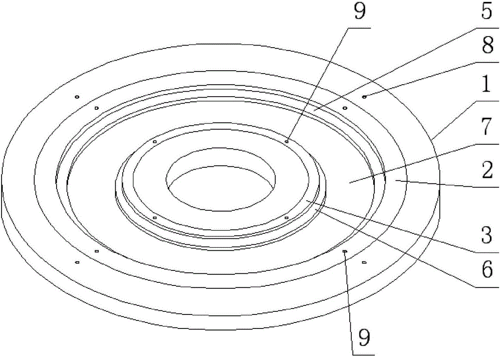
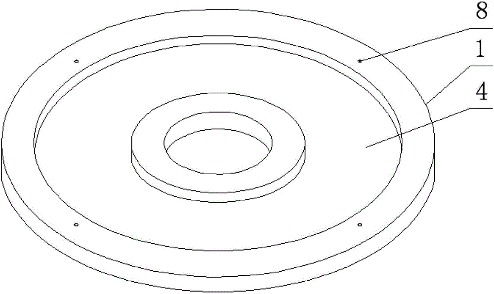
[0024] The bearing device for the trial assembly of steam turbine blades in this embodiment combines figure 1 As shown, its composition includes: a circular ring chassis 1, an outer lining ring 2 and an inner lining ring 3, the circular ring chassis 1 is a circular sheet structure, and one side surface of the circular ring chassis 1 has a groove 4. The outer ring inside the groove 4 places the outer lining ring 2, and the inner ring inside the groove 4 places the inner lining ring 3; wherein,

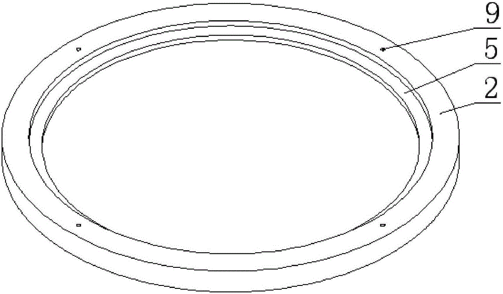
[0025] There is an inner ring shoulder 5 on the inner ring side wall of the outer backing ring 2, the thickness of the inner ring shoulder 5 is smaller than the thickness of the outer backing ring 2, and the outer backing ring 2 and the inner ring shoulder 5 form a stepped structure;

[0026] There is an outer ring shoulder 6 on the outer ring side wall of the inner lining ring 3, the thickness of the outer ring shoulder 6 is smaller than the thickness of the inner lining ring 3, and th...

specific Embodiment approach 2

[0028] The difference from Embodiment 1 is that in the bearing device for trial assembly of steam turbine blades in this embodiment, a group of lifting screw holes 8 are evenly distributed in the circumferential direction on the side of the annular chassis 1 with the groove 4 .

specific Embodiment approach 3

[0029] The difference from Embodiment 1 or Embodiment 2 is that, in the bearing device for trial assembly of steam turbine blades in this embodiment, a group of ring holes 9 are evenly distributed on the surface of the outer lining ring 2 in the circumferential direction.


PUM


Abstract

The invention discloses a bearing device for trial assembly of steam turbine vanes and an assembly method of the steam turbine vanes and belongs to an auxiliary vane assembly device. Currently, auxiliary equipment for installing vanes on an air flow channel of a steam turbine is lacked, the demounting and mounting workload is large, and the schedule is slow. According to the bearing device for trial assembly of the steam turbine vanes, a groove (4) is formed in the surface of a circular ring bottom disc (1), and an outer-layer bushing ring (2) and an inner-layer bushing ring (3) are arranged in the groove (4) to form a bearing groove (7); an inner ring shoulder (5) is arranged on the inner ring side wall of the outer-layer bushing ring (2); and an outer ring shoulder (6) is arranged on the outer ring side wall of the inner-layer bushing ring (3). The method for trial assembly of the steam turbine vanes includes the steps that the outer-layer bushing ring (2) and the inner-layer bushing ring (3) which are matched with the vanes in size are selected to be installed in the groove (4) in the circular ring bottom disc (1); the height difference of the bottom plane of the outer-ring bushing ring (2) and the bottom plane of the inner-layer bushing ring (3) is adjusted; and the vanes are put into the bearing groove (7) one by one, the assembly state of the whole circle of vanes is adjusted, and the product assembly process is achieved. The bearing device and the assembly method have the beneficial effects that the structure is simple, and installation is convenient.

Description

technical field [0001] The invention relates to a bearing device for trial assembly of steam turbine blades and an assembly method thereof. Background technique [0002] The steam flow channel of the steam turbine is realized by the steam passage formed by the whole circle of moving blades assembled on the rotor and the whole circle of stationary blades on the diaphragm and the distance along the axial direction of the steam turbine unit. Regardless of whether the moving blades are assembled or the stationary blades are welded, there will be gaps between the blades and the stationary blades. The end surfaces of the crowns or roots of the blades are misaligned, and due to the excessive grinding of the crowns or roots of a single blade, there is not enough space for the final blade to be assembled even if it is ground. If this kind of problem occurs in the product assembly process If it happens, it will bring unnecessary disassembly workload and affect the production progress ...

Claims


Application Information

Patent Timeline
Patent Type & Authority Applications(China)
IPC IPC(8): F01D25/28
CPCF01D25/285
Inventor 高岩吕宜伟吕昭易杨斌阎文松刘东滨王威韩金鑫于军丹靳朝辉
Owner HARBIN TURBINE
Why Eureka
Try Eureka