Snap together bearing isolator

a technology of bearing isolator and seal, which is applied in the direction of sealing, packaging, engine seals, etc., can solve the problems of excessive moisture and other contaminants, difficult to obtain adequate maintenance of rotating equipment, and easy to leak lubricant, etc., to prevent leakage

Inactive Publication Date: 2006-05-30
INPRO INC
View PDF10 Cites 24 Cited by
  • Summary
  • Abstract
  • Description
  • Claims
  • Application Information

AI Technical Summary

Benefits of technology

[0005]An objective of the present invention is to provide a seal around rotating shafts and between the housing and the shaft to prevent leakage of lubricant and the entry of contaminants by the use of an annular ring seal contained within a cavity formed in the stator and rotor.
[0011]The simultaneous flexing of the ramp surfaces of the rotor and stator permits the locking function when the seal members are pressed together.

Problems solved by technology

Adequate maintenance of rotating equipment is difficult to obtain because of extreme equipment duty cycles, the lessening of service factors, design and the lack of spare rotating equipment in many processing plants.
Lip seals or O-ring shaft seals can quickly wear out and fail and also permit excessive amounts of moisture and other contaminants into the oil reservoir of the operating equipment even before failure.

Method used


Image

  • Snap together bearing isolator
  • Snap together bearing isolator

Examples


Embodiment Construction

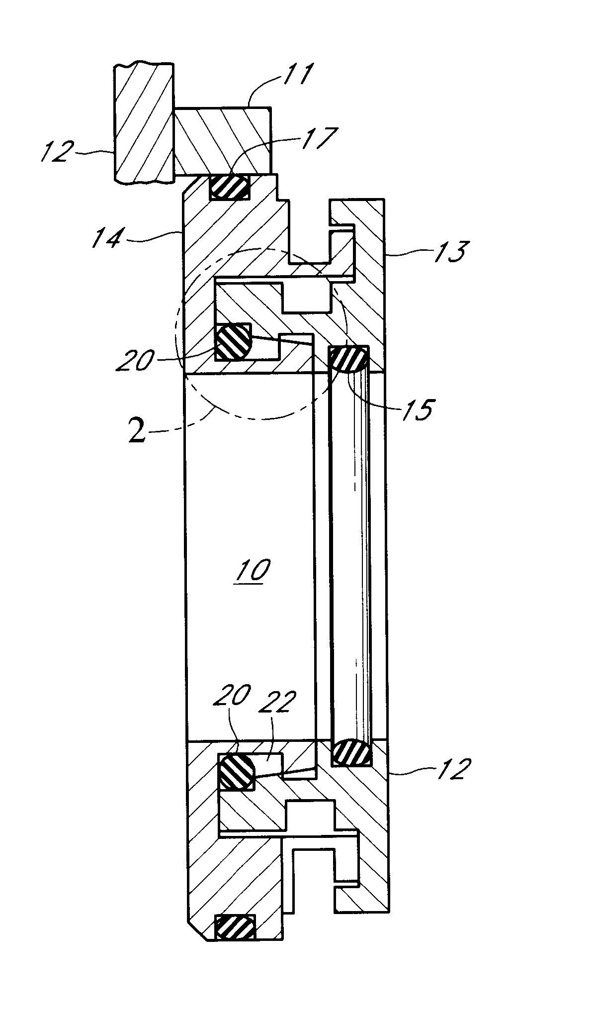
[0017]Referring first to FIG. 1. There is shown the bearing isolator including a novel locking mechanism and seal mounted on shaft 10. The shaft 10 protrudes through the isolator 18 and the housing 11 and the bearing 12. The novel isolator of this invention is shown with the stator 14 and the seal 17 holding the bearing isolator or seal 18 in position. The rotor ring 13 is affixed to the shaft by means of the frictional seal 15. The rotor ring follows the rotational movement of the shaft 10 because of the frictional engagement of the seal 15. The labyrinths and passages are substantially as shown in FIG. 1 but will not be described in detail herein because such description is readily available and found in the referenced patents. Such description is specifically found in U.S. patent application Ser. No. 09 / 139,499.

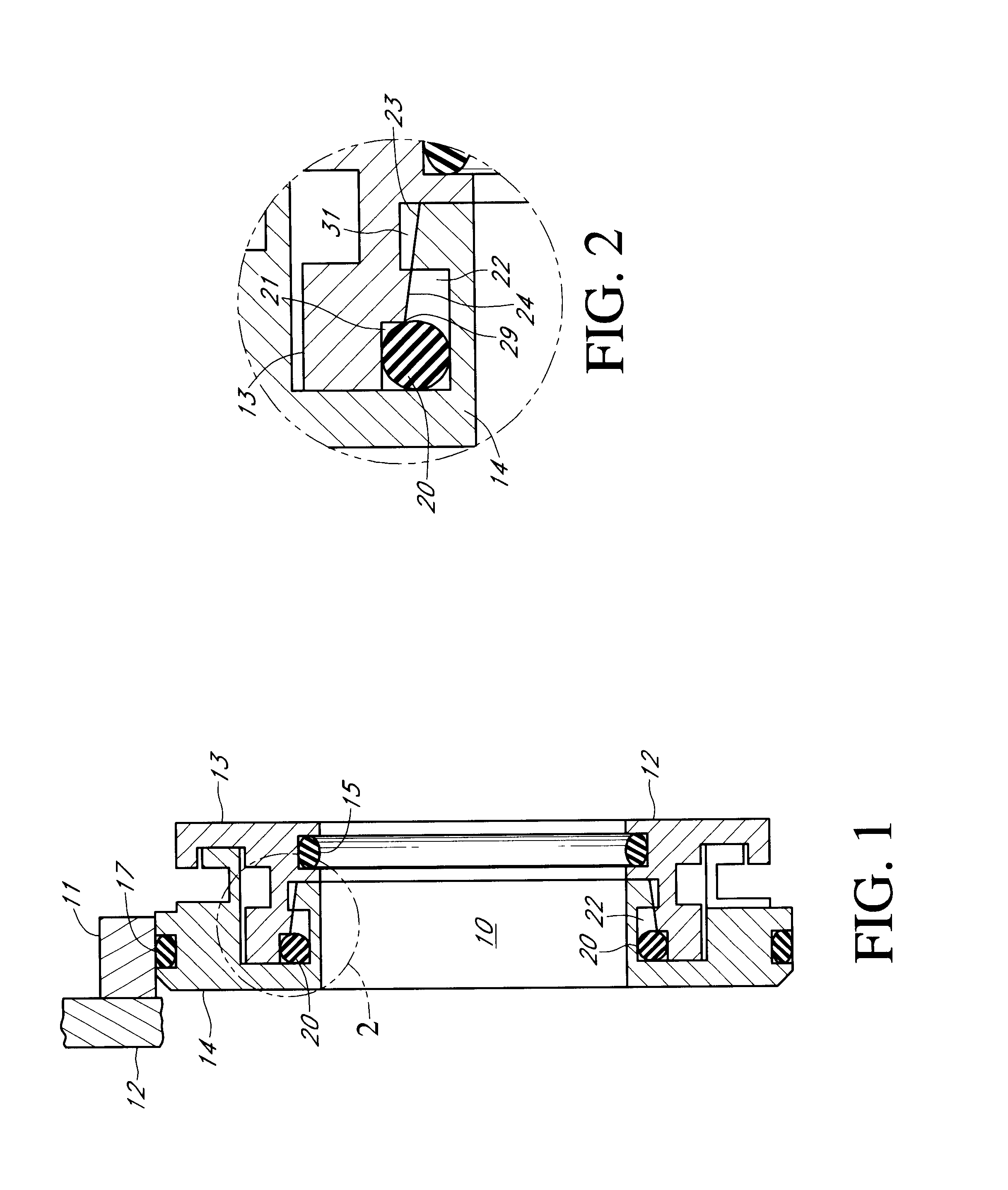
[0018]The novelty of this invention is shown in FIG. 1 but is best described by reference to FIGS. 1 and 2 together. As shown, there is a female or recess or cavity portio...


PUM


Abstract

The assembly includes rotor and stator elements each having an inclined plane or surface juxtaposed to each other. This is a metallic assembly and the rotor and stator also have juxtaposed cavities. The stator cavity being of sufficient size to accommodate a sealing member. The inclined surfaces are flexed with the inclined plane or surface of the rotor forced over the inclined plane or surface of the stator to lock the rotor and stator together with the sealing member enclosed between the rotor and stator. The sealing member does not rotate with the stator. The seal contains at least one labyrinth formed with the rotor and stator, are adjacent each other and lock together.

Description

BACKGROUND OF THE INVENTION[0001]This invention relates generally to shaft sealing devices protecting bearings for use with rotating equipment. Adequate maintenance of rotating equipment is difficult to obtain because of extreme equipment duty cycles, the lessening of service factors, design and the lack of spare rotating equipment in many processing plants.[0002]Various forms of shaft sealing devices have been utilized to try to protect the integrity of the bearing environment including rubber lip seals, clearance labyrinth seals, and attraction magnetic seals. Lip seals or O-ring shaft seals can quickly wear out and fail and also permit excessive amounts of moisture and other contaminants into the oil reservoir of the operating equipment even before failure.[0003]Labyrinth-type seals involving closely related stator and rotor rings, which do not contact each other but define labyrinth passages between them have been devised and utilized and are illustrated in Orlowski, U.S. Pat. N...

Claims


Application Information

Patent Timeline
Patent Type & Authority Patents(United States)
IPC IPC(8): F16J15/447F16J15/10
CPCF16J15/4478Y10S277/925
Inventor ORLOWSKI, DAVID C.STEINERT, WILLIAM L.
Owner INPRO INC
Why Eureka
Try Eureka