Display apparatus, light source device, and illumination unit

a technology of light source device and display device, which is applied in the direction of television system, instrument, color signal processing circuit, etc., can solve the problems of large fluctuation in led manufacturing, waste/disposal of other colors than the separated color, and inability to achieve brightness or efficiency

Inactive Publication Date: 2006-05-30
OLYMPUS CORP
View PDF14 Cites 105 Cited by
  • Summary
  • Abstract
  • Description
  • Claims
  • Application Information

AI Technical Summary

Problems solved by technology

In fact, a plurality of high-efficiency high-luminance LEDs have started to be practically used in a traffic signal lamp, large-sized full-color display for outdoors, various lamps for automobiles, and a backlight of a liquid crystal display of a cellular phone, although the practical use has heretofore been impossible in respect of brightness or efficiency.
With the use of the white system light emitting source, since only one desired color is separated and used, colors other than the separated color are wasted / discarded by the filter in many cases.
However, the LED has a large manufacturing fluctuation.
Even when the same current is supplied to the LED, a constant brightness cannot be obtained in many cases.
Moreover, a full-color display panel in which the LEDs of three primary colors of red, green, and blue are incorporated has a problem that the fluctuation of an emission intensity of each LED device is large and a uniform shade cannot be achieved.
Furthermore, usual red, green, and blue system LEDs have a problem that each deterioration characteristic differs.

Method used


Image

  • Display apparatus, light source device, and illumination unit
  • Display apparatus, light source device, and illumination unit
  • Display apparatus, light source device, and illumination unit

Examples


first embodiment

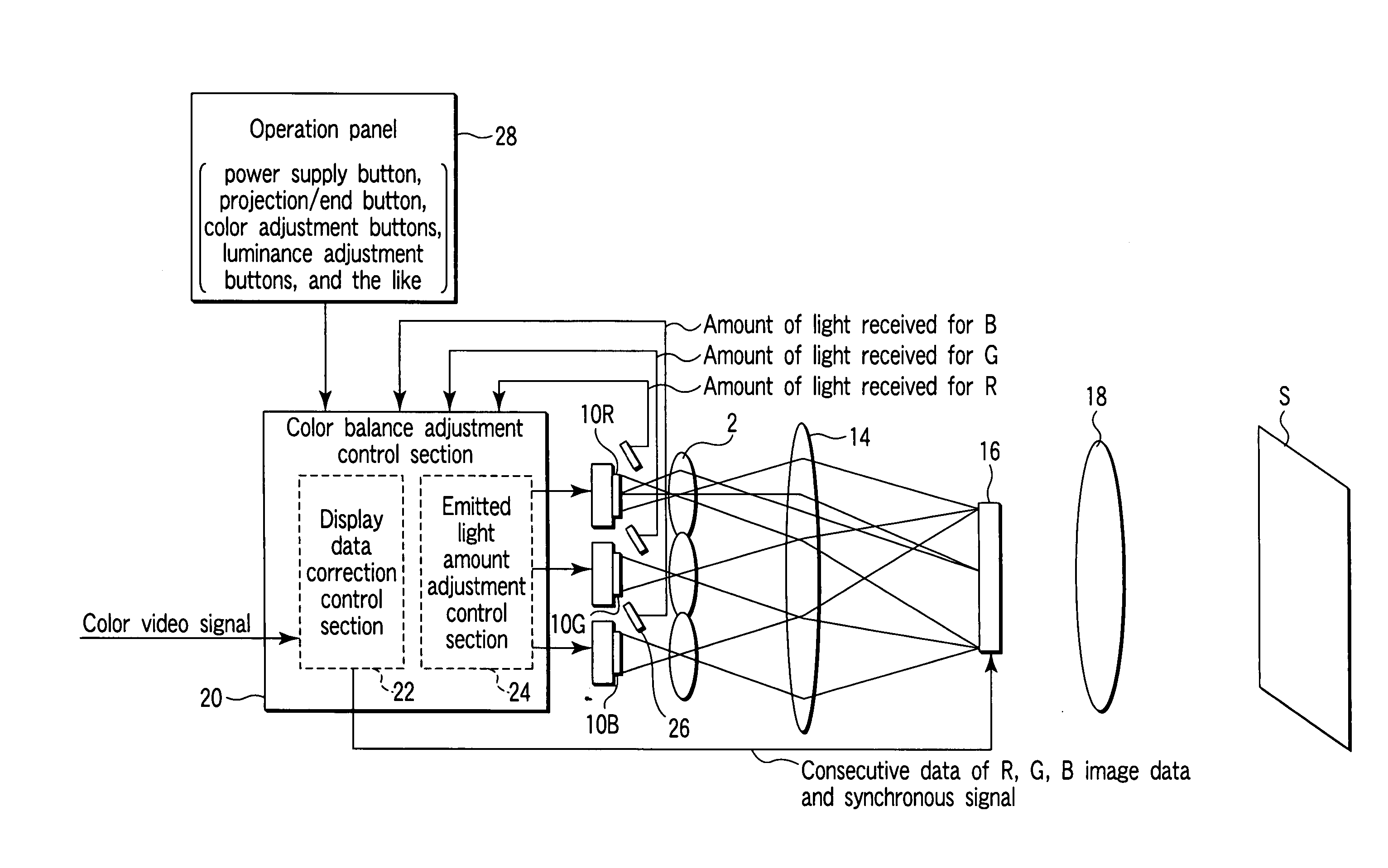
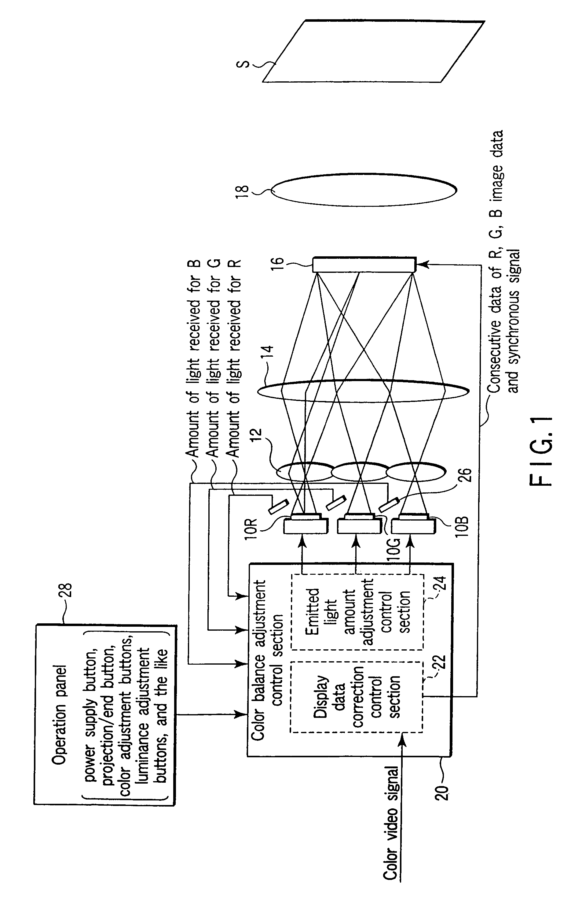
[0066]As shown in FIG. 1, in a display apparatus according to the present invention, output light from a plurality of LEDs 10 (R-LED 10R, G-LED 10G, and B-LED 10B) different from one another in emitted light color is taken out by a light distribution lens array which includes light condensing optical systems 12 for the respective LEDs 10. Moreover, the light from the plurality of LEDs 10 is superimposed upon a light modulation device 16 by a superposition lens 14. This constitution is similar to a projector device disclosed in U.S. Pat. No. 6,227,669 B1. Moreover, in the display apparatus, an image is displayed on the light modulation device 16 such as a transmission type LCD, and accordingly the displayed image is enlarged / projected on a screen S whish is the display plane by a projection lens 18.

[0067]Here, the image displayed on the light modulation device 16 is each image data of R, G, B generated from a color video signal inputted into the display apparatus in a color balance a...

third embodiment

[0126]As shown in FIG. 23, the display apparatus has substantially the same constitution as that shown in FIG. 20, but an LED substrate 48 on which the respective LEDs 10 are mounted is integrally constituted. Moreover, temperature sensors 50 are disposed on the surface (back surface) of the LED substrate 48 opposite to an LED mounting surface.

[0127]As shown in FIG. 24, the color balance adjustment control section 20 is constituted of a bus 52, CPU 54, ROM 56, RAM 58, video input section 60, memory for display 62, LCD control circuit 64, LED lighting control circuit 66, flash memory 68, and TIMER 70. Moreover, the CPU 54 is connected to the ROM 56, RAM 58, memory for display 62, LED lighting control circuit 66, flash memory 68, and TIMER 70 in the color balance adjustment control section 20, and the light receiving device 26, operation panel 28, and temperature sensors 50 outside the color balance adjustment control section 20 via the bus 52.

[0128]Here, the CPU 54 controls the whol...

fourth embodiment

[0172]Next, the present invention will be described. In the present embodiment, a light source device in a replaceable mode is incorporated in the display apparatus. That is, as shown in FIG. 36, for a light source device 72 according to the present embodiment, a substrate on which each LED 10 is mounted is constituted integrally with the LED substrate 48, the temperature sensors 50 are disposed on the surface (back surface) of the LED substrate 48 opposite to the LED mounting surface, and further the flash memory 68 is mounted on the back surface. In this constitution, these LED 10, LED substrate 48, temperature sensors 50, and flash memory 68 are integrally replaceable.

[0173]That is, this device is replaced by the unit of the LED substrate 48 in order to easily replace the device with the deterioration or failure of the LED 10 which is the light source. Moreover, for the LED substrate 48 which is a replacement component, in addition to the LEDs 10 of R, G, B, the flash memory 68 i...


PUM


Abstract

A display apparatus capable of illuminating a light modulation device with a light from a light emitting body to display an image on a display plane comprises a plurality of light emitting bodies (R, G, B) different from one another in emitted light color, a light receiving device configured to detect the light from the light emitting bodies and to output an amount of light received, and a color balance adjustment control section configured to adjust and control a color balance in the display plane in accordance with the amount of light received by the light receiving device. The color balance adjustment control section is configured to be capable of identifying the emitted light color of the light emitting body relating to the amount of light received.

Description

CROSS-REFERENCE TO RELATED APPLICATIONS[0001]This application is based upon and claims the benefit of priority from the prior Japanese Patent Application No. 2002-353902, filed Dec. 5, 2002, the entire contents of which are incorporated herein by reference.BACKGROUND OF THE INVENTION[0002]1. Field of the Invention[0003]The present invention relates to a display apparatus capable of illuminating a light modulation device with a light from light emitting bodies such as a light emitting diode (hereinafter abbreviated as LED) to display an image on a display plane, a light source device for use in the display apparatus, and an illuminating unit which illuminates a region to be irradiated with the light from the light emitting body.[0004]2. Description of the Related Art[0005]Nowadays, an LED has won remarkable attention as a next-generation small-sized light emitting source. The LED has heretofore had advantages such as a small size, high resistance, and long life, but has mainly been u...

Claims


Application Information

Patent Timeline
Patent Type & Authority Patents(United States)
IPC IPC(8): G03B21/00G03B21/14G03B21/26H04N5/64H04N9/31F21V9/00G09G3/20G09G3/34G09G3/36H01L31/12H01L33/58H04N9/73H05B37/02
CPCG09G3/3413H04N9/315H04N9/73G09G2320/041G09G2320/048G09G2320/0666G09G2360/145
Inventor MATSUI, SHINZO
Owner OLYMPUS CORP
Why Eureka
Try Eureka