Light source, and projector provided with the light source

a technology of projector and light source, which is applied in the field of light source, can solve the problems of inability to achieve good cooling effect and ventilation efficiency, inability to meet luminance and size reduction of related art lamps, and high heat density of lamps, so as to increase the luminance of the projector, reduce the noise of the cooling fan, and reduce the number of revolutions of the cooling fan.

Active Publication Date: 2006-05-30
SEIKO EPSON CORP
View PDF13 Cites 16 Cited by
  • Summary
  • Abstract
  • Description
  • Claims
  • Application Information

AI Technical Summary

Benefits of technology

[0013]On the other hand, by increasing the blowing amount to the lamp by a cooling fan, the cooling effect and the ventilation efficiency are heightened, sufficiently high luminance and size reduction for related art lamps are met, and a long lamp life is realized. However, in this case, the number of revolutions of the cooling fan increases, so that there is a problem that noises made when the fan is on become high.
[0053]In case that the light source of the invention is used as the light source of this projector, further increase of luminance of the projector is made possible. Further, the number of revolutions of the cooling fan can be reduced, so that the noise of the cooling fan can be reduced.

Problems solved by technology

Therefore, good cooling effect and ventilation efficiency cannot be obtained.
As a result, heat density of the lamp becomes high, so that there has been a problem that sufficiently high luminance and size reduction for related art lamps cannot be met, and that a long lamp lifetime cannot be realized.
Further, though a mesh having a comparatively high opening rate can be used, the strength of the mesh lowers in this case.
Therefore, there is a problem that the mesh is broken off by collision with scattered glass pieces when the lamp has burst.
Therefore, a mesh having a comparatively high opening rate cannot be used.
However, in this case, the number of revolutions of the cooling fan increases, so that there is a problem that noises made when the fan is on become high.

Method used


Image

  • Light source, and projector provided with the light source
  • Light source, and projector provided with the light source
  • Light source, and projector provided with the light source

Examples


exemplary embodiment 1

A-1. Exemplary Embodiment 1

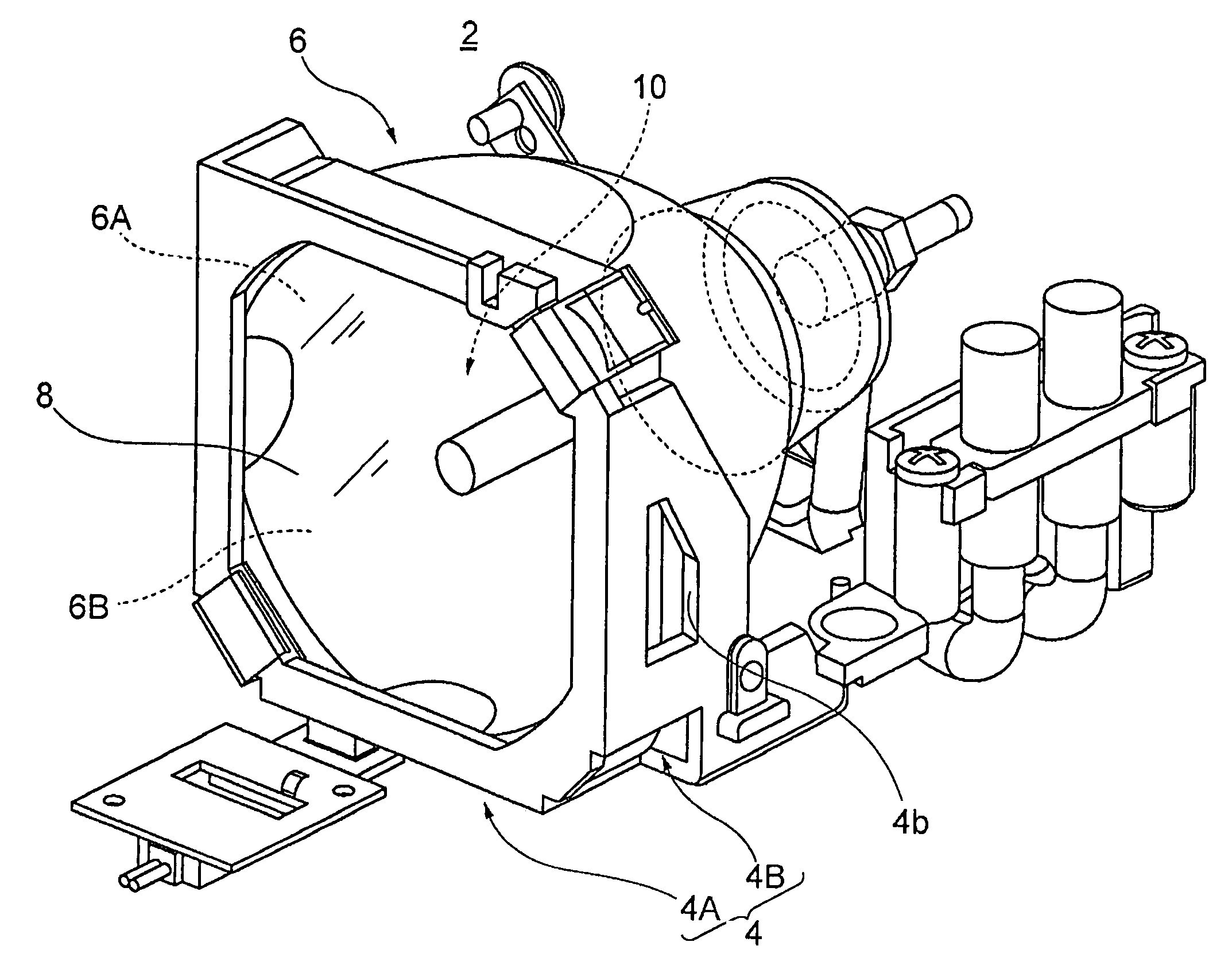
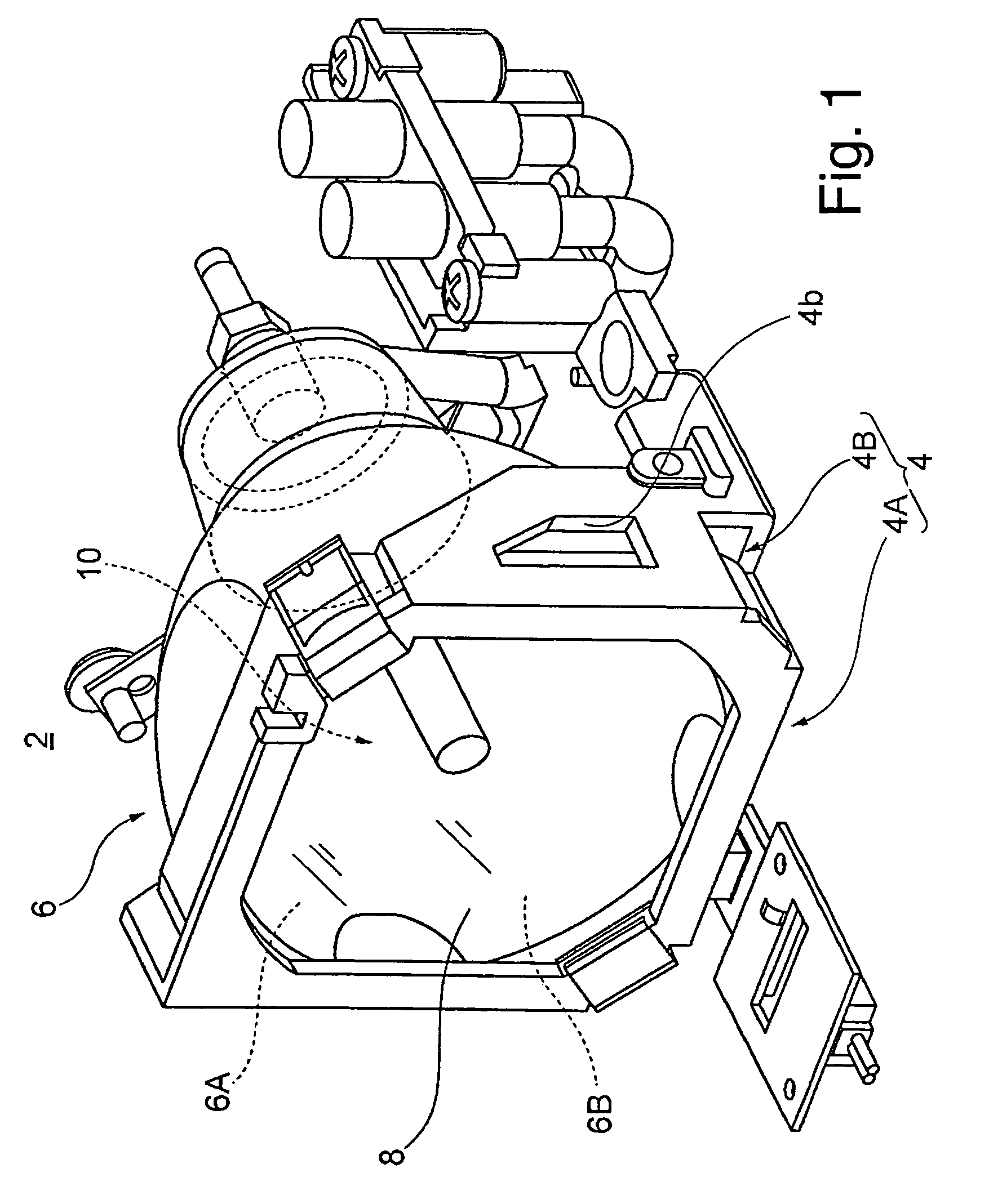
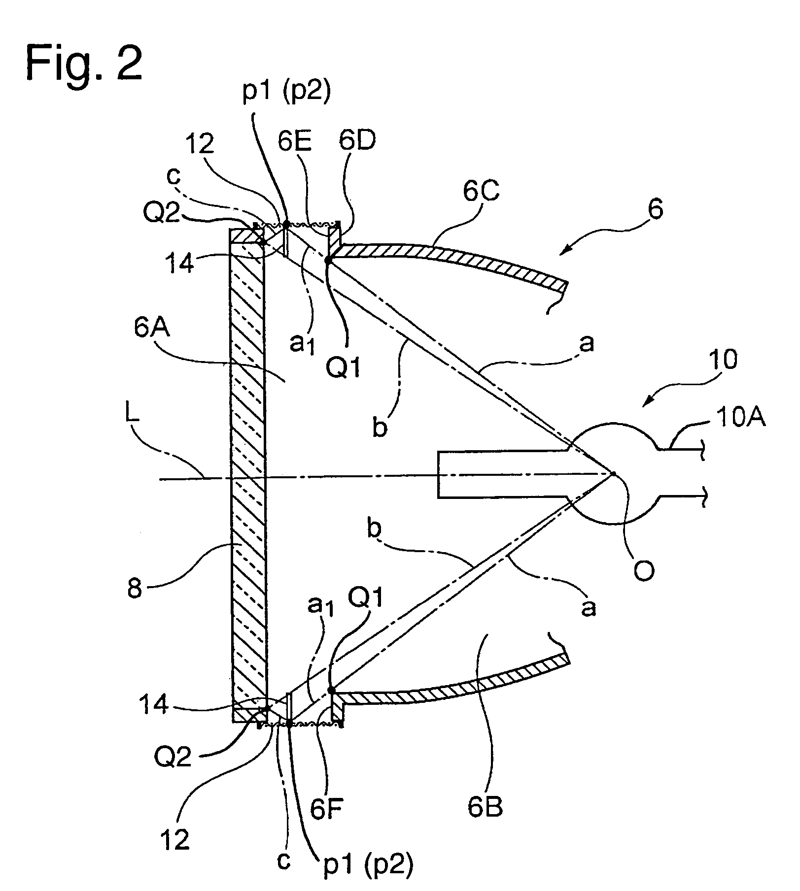
[0065]FIG. 1 is a perspective view showing the entire light source according to a first exemplary embodiment of the invention. FIG. 2 is a sectional view showing a significant portion of the light source according to the first exemplary embodiment. FIG. 3 is an exploded perspective view showing an attachment state of a protective wall in the light source according to the first exemplary embodiment.

[0066]FIGS. 4(a) and 4(b) are enlarged plan views showing the entire mesh and a part of the mesh in the light source according to the first exemplary embodiment.

[0067]As shown in FIG. 1, a light source 2 is roughly composed of a lamp housing 4, a concave mirror 6, a light permeable member 8, and a lamp 10.

[0068]The lamp housing 4 includes a frame part 4A which opens in the front and back directions, and sidewall parts 4B connected to this frame part 4A, and the entire housing 4 is formed of a high heat-resistant member having a substantial C-shaped section. On bo...

exemplary embodiment 2

A-2. Exemplary Embodiment 2

[0085]FIG. 5 is a sectional view showing a significant portion of a light source according to a second exemplary embodiment of the invention.

[0086]FIG. 6 is an exploded perspective view showing an attachment state of a protective wall and an auxiliary protective wall in the light source according to the second exemplary embodiment of the invention. In FIGS. 5 and 6, the same members as those in FIGS. 2 and 3 are denoted by the same reference numerals, and their detailed descriptions are omitted.

[0087]In the first exemplary embodiment, the protective wall 14 is provided in the position where it is possible to prevent, both lamp broken pieces that have scattered toward the mesh 12 and lamp broken pieces that have collided with the light permeable member 8 and bounced, from directly colliding with the mesh 12. On the contrary, the light source shown in this exemplary embodiment is provided such that: a protective wall 14 is provided in a position where it is ...

exemplary embodiment 3

A-3. Exemplary Embodiment 3

[0097]In the second exemplary embodiment (FIGS. 5 and 6), only one auxiliary protective wall is provided. However, as shown in FIG. 7, plural auxiliary protective walls 82, 84 may be provided on a light permeable member 8 side of a protective wall 14 in parallel. This exemplary embodiment is different from the second exemplary embodiment in that the plural auxiliary protective walls 82, 84 are provided. Other features are similar to that in the second exemplary embodiment. FIG. 7 is a sectional view showing a significant portion of a light source according to a third exemplary embodiment. In FIG. 7, the same members as those in FIG. 5 are denoted by the same reference numerals, and their detailed descriptions are omitted.

[0098]As shown in FIG. 7, a light source 70 in this exemplary embodiment includes a concave mirror 72, a light permeable member 8 and a lamp 10.

[0099]The auxiliary protective walls 82 and 84 are arranged in positions where direct collision...


PUM


Abstract

The invention provides a light source and a projector with sufficiently high luminance and size reduction for related art lamps, an increased lamp lifetime, and reduced noises from a cooling fan. A light source includes a concave mirror which has a reflecting part that reflects light, non-reflecting parts adjacent to this reflecting part, and permeable ports that pass through the non-reflecting parts, and which opens forward; a lamp which is arranged in this concave mirror and emits the light; and a light permeable member which covers the opening part of the concave mirror. The concave mirror includes a mesh arranged in a position where it covers the permeable port, and a protective wall to protect the mesh, which is arranged in a position where direct collision between the mesh and broken pieces of the lamp made by a burst of the lamp is reduced or prevented.

Description

BACKGROUND OF THE INVENTION[0001]1. Field of Invention[0002]The present invention relates to a light source having a lamp, such as a high-pressure mercury lamp or a metal halide lamp, and a projector provided with this light source.[0003]2. Description of Related Art[0004]A related art projector includes an illuminating optical system having a light source which emits an illumination light, an electro-optic modulator which modulates the illumination light from this illuminating optical system according to image signals, and a projecting optical system which projects and displays the light modulated by this electro-optic modulator as a display image on a screen.[0005]For such a projector, it is required that the projected image (display image) be light, the luminous intensity of the illumination light be high, and the color balance be good.[0006]Therefore, in order to obtain a higher luminous intensity, a related art illuminating optical system is often provided with a light source h...

Claims


Application Information

Patent Timeline
Patent Type & Authority Patents(United States)
IPC IPC(8): G03B21/14B60Q3/04G03B21/20G03B21/22G03B21/28F21Y101/00H04N9/31
CPCH04N9/3105H04N9/3144G03B21/2086H04N9/3197H04N9/315G03B21/16G03B21/14
Inventor KATSUMA, RYOJIFUJIMORI, MOTOYUKI
Owner SEIKO EPSON CORP
Why Eureka
Try Eureka