Spread illuminating apparatus of side-light type

a technology of illuminating apparatus and sidelight, which is applied in the direction of lighting and heating apparatus, identification means, instruments, etc., can solve the problems of insufficient workability, short circuit, and insufficient skill to obtain the desired assembly accuracy, and achieve the effect of ensuring the strength required for the illuminating apparatus

Inactive Publication Date: 2006-05-30
MINEBEA CO LTD
View PDF6 Cites 12 Cited by
  • Summary
  • Abstract
  • Description
  • Claims
  • Application Information

AI Technical Summary

Benefits of technology

[0015]The present invention has been made in light of the above problems, and it is an object of the present invention to obtain a more efficient workability and a more consistent accuracy for assembling the spread illuminating apparatus.
[0016]It is another object of the present invention to make the light conductive plate and the reflection type liquid crystal display element (not shown) in contact with the front face of the concerned electronic product so as to improve the visibility as the display device without sacrificing the strength.

Problems solved by technology

However, the conventional spread illuminating apparatus 1 of the above configuration creates the following problems.
As a result, great skill is essentially required to obtain a desired assembly accuracy, and the workability is not so good.
Further, if the FPC is also fixed at a position deviated from a predetermined position as a result of the light source 12 deviating from its correct position, a short-circuit can occur due to the contact with other metal components.
Third, since the reinforcing frame 21 is made of a sheet metal, and it is generally more difficult to control the accuracy of this reinforcing frame than the resin-molded one.
However, a problem occurs in that it is more difficult to secure the strength of the structure using the reinforcing plate 24 than that of a structure using the reinforcing frame 21 U-shaped in section.

Method used


Image

  • Spread illuminating apparatus of side-light type
  • Spread illuminating apparatus of side-light type
  • Spread illuminating apparatus of side-light type

Examples


Embodiment Construction

[0034]Preferred embodiments of the spread illuminating apparatus according to the present invention will be hereinafter explained referring to the attached drawings. The components identical with or corresponding to those in the conventional spread illuminating apparatus are represented by the same reference numerals and the detailed description thereof is omitted.

[0035]In the description, the terms “top surface”, “bottom surface”, “side surface”, “above”, “below” and “at the side of” are used to express the positional relationship of each component in FIG. 3 for the convenience of the description. Thus, when the spread illuminating apparatus according to the embodiment of the present invention is incorporated into any electronic product such as personal computers and cellular phones, and is put into practical use, the “top surface” is not necessarily above the “bottom surface”.

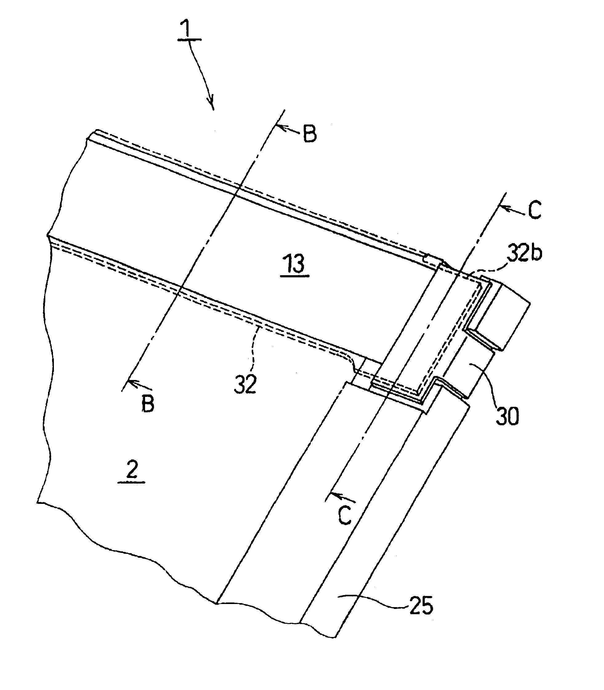
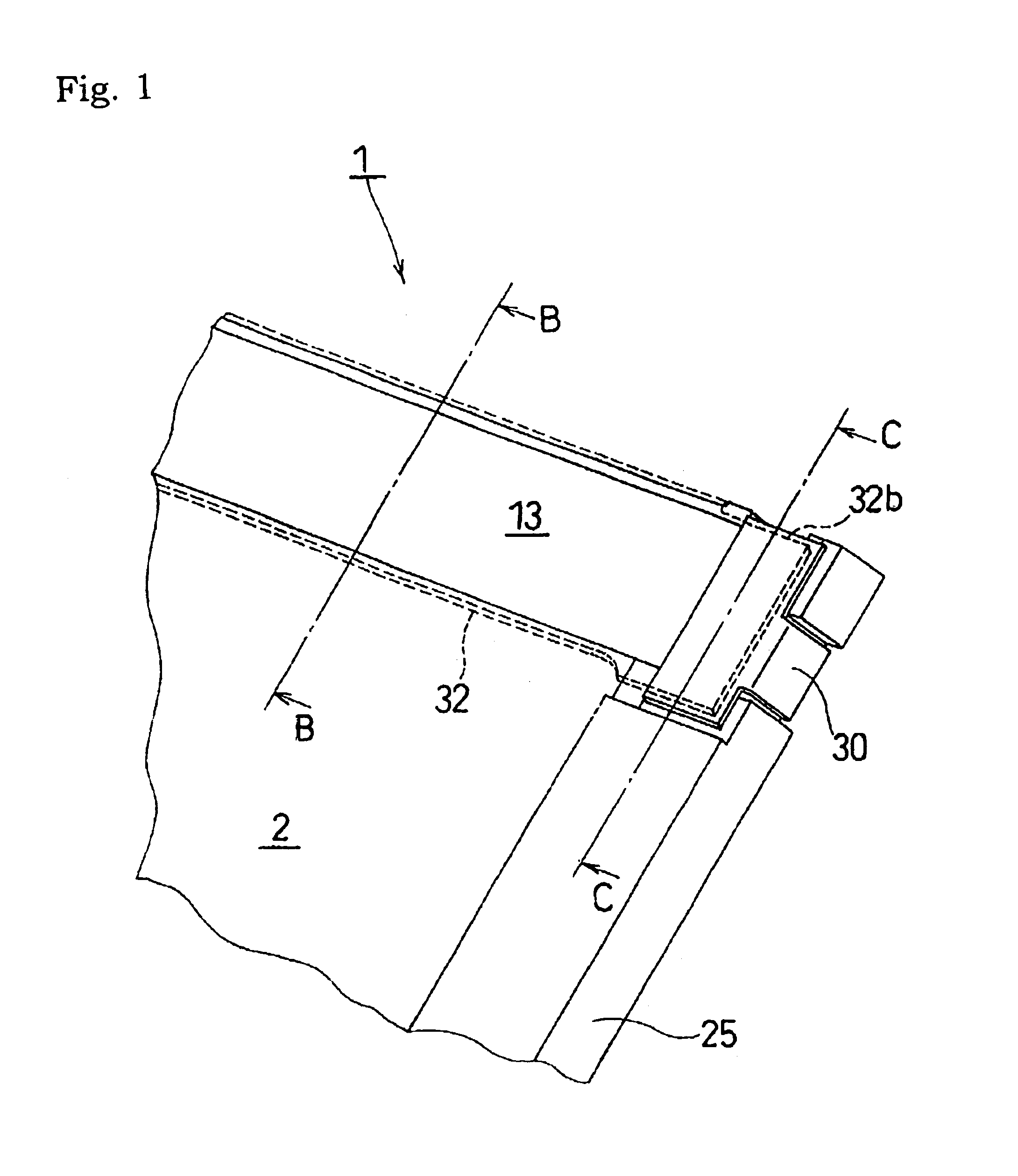
[0036]Referring to FIGS. 1, 2, 3A and 3B, the spread illuminating apparatus 1 includes a housing frame 25 ...


PUM

PropertyMeasurementUnit
thicknessaaaaaaaaaa
thicknessaaaaaaaaaa
light conductiveaaaaaaaaaa

Abstract

A housing frame includes a recess, a flat seat portion and a frame-shaped seat portion which are positioning units for a spot-like light source, a light conductive bar and a light conductive plate, respectively. The required assembly accuracy can be reliably obtained by fitting the light source, the light conductive bar and the light conductive plate to the predetermined positioning units of the housing frame. A recess and a flat seat portion have a thickness D2 smaller than the thickness D1 of a frame forming the positioning unit for the light conductive plate, and the housing frame forms a cavity, an opening of which is directed upward, and in order to obtain the required strength a reinforcing frame is provided. By reducing the thickness of the reinforcing frame, the light conductive plate can be disposed close to a display surface of any electronic product in incorporating the spread illuminating apparatus into any the electronic product.

Description

BACKGROUND OF THE INVENTION[0001]1. Field of the Invention[0002]The present invention relates to a spread illuminating apparatus of side-light type used as an illuminating means for a liquid crystal display device.[0003]2. Description of the Related Art[0004]A liquid crystal display (hereinafter, referred to as “LCD”) characterized by its low power consumption, low profile and light-weight has been extensively used as the display mainly for applications of personal computers and cellular phones, and the demand therefor has been increasing. Since a liquid crystal which is a structural element of the LCD does not emit light by itself unlike a light emitting type element such as a CRT, the LCD requires a separate illuminating means for observing an image. In particular, to satisfy great demand for thinning the apparatus and for the apparatus with a lower electric power consumption in recent years, a sheet-like spread illuminating apparatus of side-light type (light conductive plate typ...

Claims


Application Information

Patent Timeline
Patent Type & Authority Patents(United States)
IPC IPC(8): F21V7/18F21V8/00G02F1/1333F21Y101/02G02B6/00G02F1/13357G09F9/00
CPCG02B6/0086G02B6/0028G02B6/0031G02B6/0061G02B6/0038
Inventor KAWASHIMA, SATOSHINISHIOKA, AKIHISA
Owner MINEBEA CO LTD
Why Eureka
Try Eureka